NEST
NEST (Nested Elements and System Tolerancing) tool is designed to improve and simplify the definition of position tolerances for complex systems. Users can define groups of surfaces, specify and visualize pivot points, and use names for commonly used pivot locations.
This tool is available in sequential mode only.
Accessing NEST
NEST is available in sequential mode only.
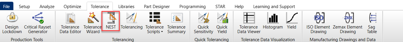
- Go to Tolerance tab in the ribbon.
- Click NEST in the tolerancing section.
Understanding the NEST interface
Groups
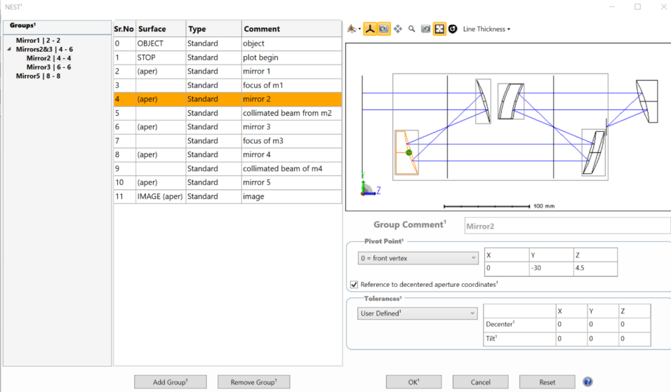
The Groups section, located on the left side of the window, presents a tree view of groups defined by the user. These groups are created by selecting surfaces from the list of surfaces to the right of the tree and by clicking the Add Group button.
Additonally, group names can be modified by either double-clicking or right-clicking on the group name.
Grouping Rules and Behavior
Groups must consist of contiguous surfaces. The tool automatically enforces nesting and ordering rules, allowing users to define groups in any order.
Additonally, smaller groups, when applicable, are nested within larger ones. Surfaces cannot be repeated within groups at the same level, and overlapping groups are not permitted. The object and image surfaces are excluded from group definitions.
Add Group Clicking this button will add the highlighted line(s) of the list of surfaces into a new group. If no lines have been highlighted, the button is inactive. Multiple lines can be highlighted at the same time.
Remove Group Clicking this button will remove the highlighted group(s) from the tool.
Layout plot
The 2D layout of the lens is plotted at the top-right corner of the interface. The individual components are surrounded by a bounding box that marks the extent of that component. Surfaces are highlighted in the selected group. Pivot points are shown for selected groups and the size of the pivot points can be controlled in LineThickness/Points drop down in the toolbar of the layout.
Pivot Point
Additionally, the user can define the pivot point type, position, and tolerances for each element in the bottom right section of the interface.
- Front vertex – This point is located at the front vertex of the surface, in local surface coordinates.
- Rear vertex – Vertex of the last surface in the group. For mirrors, this point is located at the back of the substrate, if one is defined.
- Front mechanical edge – Positions the pivot point at the first surface in the group, with Z = sag of the surface at the edge of the circular aperture (if used) or at the edge of the Clear Semi-diameter.
- Rear mechanical edge - Positions the pivot point at the last surface in the group, with Z = sag of the surface at the edge of the circular aperture (if used) or at the edge of the Clear Semi-diameter. For mirrors, the substrate is considered.
Pivot point X, Y, and Z coordinates are calculated with respect to the vertex of the first surface in the group.
Reference to decentered aperture coordinates This option is available only for groups that include a single mirror. When checked, the "Front Vertex" will be positioned at the vertex of the decentered aperture, and the "Rear Vertex" will be positioned at the back of the mirror substrate, and User-Defined will be referenced to the decentered aperture vertex. (See Draw section in Draw Surface Properties of the LDE for substrate definition).
Tolerances
- Commercial
- Precision
- High Precision
- Cell Phone Lens
- User Defined
Reset
Clicking Reset resets any defined nested elements as well as tolerance settings to the default (no nested elements).
Cancel
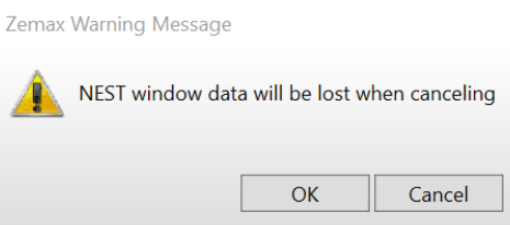
Clicking Cancel closes the tool, any changes are lost. The following message will appear.
OK
Clicking OK triggers running of NEST.
Limitations and restrictions
- NEST currently does not support multi-configuration files. Users should reduce files to one configuration before applying NEST.
- Systems that use tilts and decenters in the surface Properties (rather than Coordinate Breaks) may return unexpected results. Similarly, systems that use Coordinate Returns should be checked carefully, since the values are updated continually.
- Composite surfaces are not fully supported. Users should make sure that Add-on surfaces are not separated from the Base surface in a Composite stack.
- Named pivot points, such as "Front Vertex" and "Rear Vertex" are calculated for Circular Apertures only. Otherwise, the Clear Semi-Diameter value is used to calculate the Z location of the pivot. Z values for Front and Rear Mechanical Edges are calculated along the +X axis at the edge of the aperture.
- For the "Reference to decentered aperture coordinates" option, all aperture types with decenters are supported except for UDAs (User Defined Apertures). If the option is checked, only Front and Rear Vertex and User-defined pivots are available.
- Rear vertex and rear mechanical edge for fully 3-dimensional groups will only return a Z coordinate, users may use the User Defined option to move the pivot to the intended location.
- User-defined pivot values are not yet written into the Lens Data Editor when using NEST. A fix is planned for a future release. As a temporary workaround, enter any required pivot adjustments directly into the inserted Coordinate Break rows in the Lens Data Editor. Z decenter values should be places in the Thickness column.
Validation
To ensure the accuracy and reliability of results generated by NEST, it is important to validate its output.
- The performance of the system (spot diagrams, etc.).
- Global coordinates of the original surfaces. This can be done conveniently in the Merit Function Editor using GLCX, GLCY, and GLCZ operands.
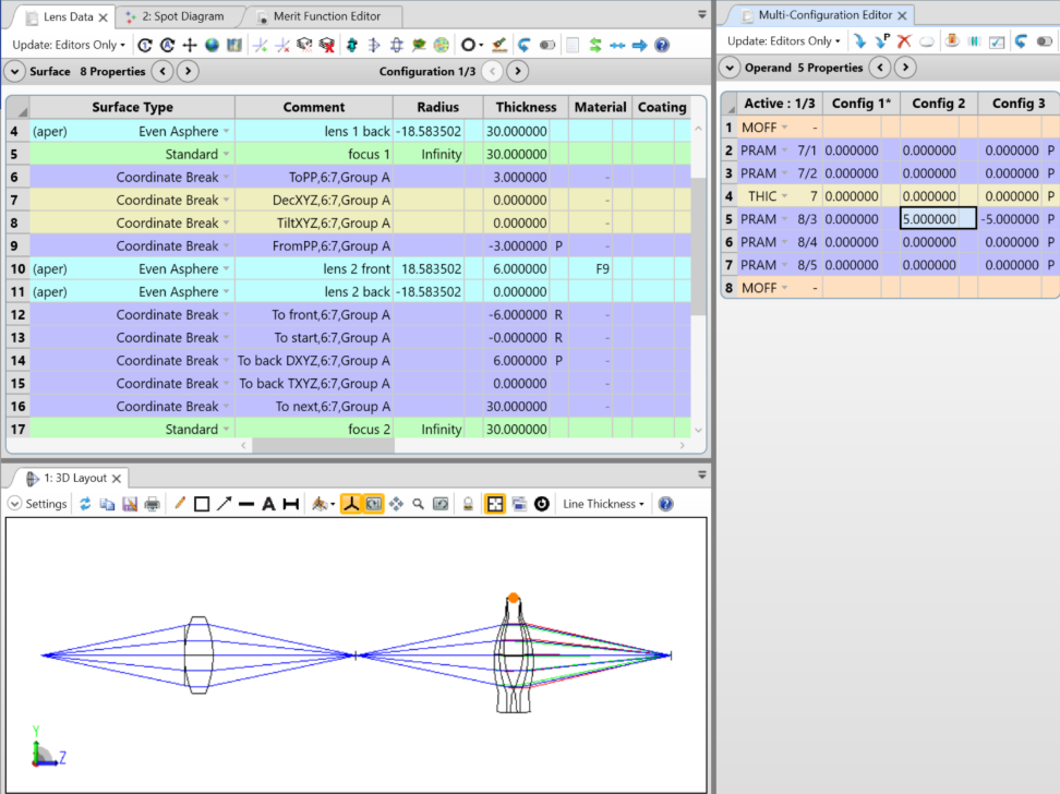
The behavior of the pivot points may be visually validated by using the Multi-configuration Editor to control the tilts and decenters in the "DecXYZ" and "TiltXYZ" rows, as shown below. In a 3D Layout, all configurations can be plotted simultaneously so that the position changes of the surfaces can easily be seen.
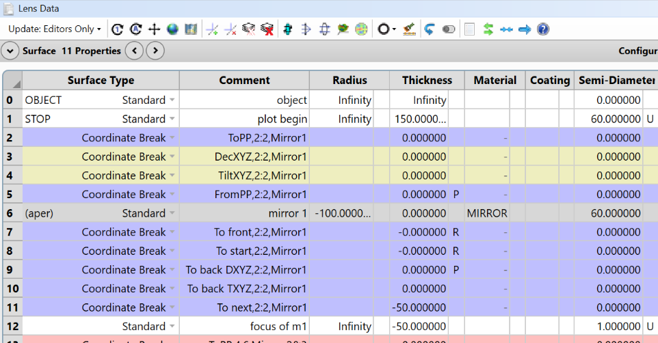
When the NEST tool executes, Coordinate Break surfaces are added to the LDE, as shown below. Inserted CBs (Coordinate Breaks) are color-coded. Four CBs before a surface, and 5 after. The two rows shown in yellow, "DecXYZ" and "TiltXYZ" are the rows used to tilt and decenter the part during tolerancing and Monte Carlo simulations. All values in these rows are 0 until tolerancing is run. The remaining CBs are used to position the pivot points.
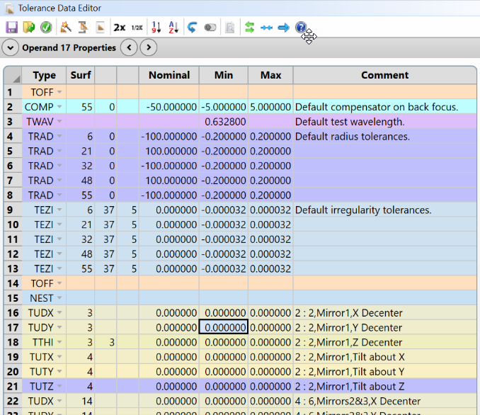
Changes to the Tolerance Data Editor Running NEST adds a NEST operand and tilt and the following decenter operands: TUDX, TUDY, THIC, TUTX, TUTY, and TUTZ as shown below.
NEST changes will not over-write existing operands. Instead, it adds a NEST operand at the end and decenter operands after the NEST operand.