


Tutorial 2: Building a Prism from Sketches (using part designer)
In this tutorial, users will utilize the various sketch features within the Zemax Part Designer and learn to optimize a part within the OpticStudio environment.
User's will create a simple Schmidt-Pechan Roof Prism using the line segment tool as shown below:
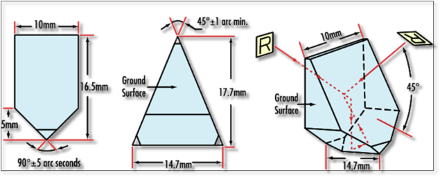
A Schmidt-Pecan Prism and its dimensions.
Step I: Drawing the Pentagonal Base Shape
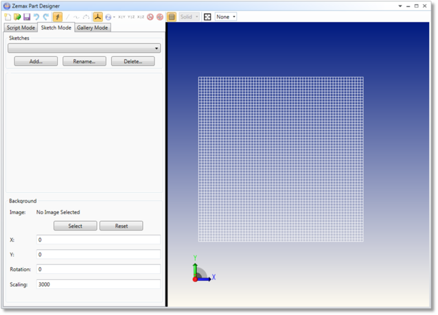
Begin by opening the Zemax Part Designer and navigating to the sketch mode.
Add a single sketch to the part file by clicking the "Add..." button located below the empty sketch list. This will add an empty sketch entitled "Sketch1" to the list box. Rename this sketch to "pentagon" by clicking the "Rename..." button next to the "Add..." button.
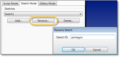
Press "OK" to rename the sketch after entering a valid text string.
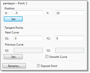
Begin the sketch by selecting the Line Tool located along the tool bar at the top of the screen. Plot the following points in the order shown below. You can plot the approximate locations and set values afterword via the Point Control Panel.
Point 1: (-5.000, 10.000)
Point 2: (5.000, 10.000)
Point 3: (5.000, -1.500)
Point 4: (0.000, -6.515)
Point 5: (-5.000, -1.500)
Point 6: (-5.000, 10.000)
Return ZPD into script mode and type the following command into the script editor:
EXTRUDE baseShape, pentagon, 0, 20
The command instructs ZPD to create an extruded shape, "baseShape", utilizing the sketch, "pentagon", with a draft angle of 0° and a length of 20 along the positive Z-axis (extrusions will always begin at the origin and protrude along the positive Z-axis).
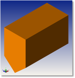
The extruded pentagon extending 20 units out of the origin along the +Z-Axis
Thinking ahead, the final prism must be a triangular cut from the "baseShape" geometry. As all extrusions extend along the +Z-axis, baseShape must be rotated 90° about the y-axis and centered at the origin. Modify the entire script to the following and rebuild:
CONSTANT length, 20
EXTRUDE baseShape,pentagon,0,length
MOVE baseShape, 0,0,-(length/2)
ROTATE baseShape, 90, 0, 1,0
The variable indicating the length of the extrusion is reprogrammed as a CONSTANT as to be able to modify the length of the extrusion at any time. The variable is not initialized as a PARAMETER because the value used is fairly arbitrary and does not need to be modified within the OpticStudio Environment.
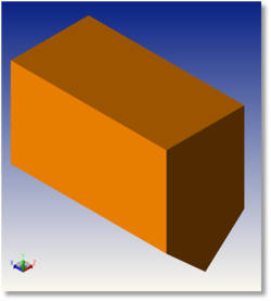
The baseShape is rotated and offset so that the middle of the part is at the origin
Step II: Creating a Triangular Cut
Re-enter Sketch Mode and add a new Sketch titled, "triangle". Using the line tool, plot the following points:
Point 1: (0.000, 11.000)
Point 2: (-7.350, -6.515)
Point 3: (7.350, -6.515)
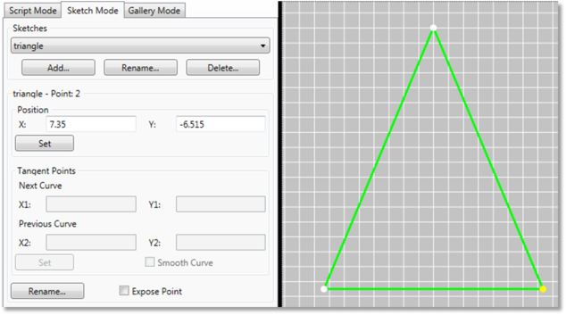
Plotting the control points for the triangle cross section.
Navigate back to Script Mode and enter the following commands:
EXTRUDE cut,triangle,0,length
MOVE cut, 0,0,-length/2
OVERLAP final, baseShape, cut
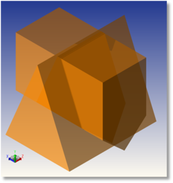
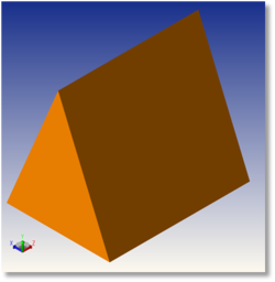
The extruded part is created with the specified length, centered, and cut from the initial baseShape Object.
The Schmidt-Pechan Roof Prism is now complete.
Step III: Optimizing the part within OpticStudio
Depending on the user's usage of the resulting part, there are several ways in which this part can be optimized. In the case of this particular part, light typically passes from one pentagonal face of the prism to the other. One primary factor in this behavior is the angle adjoining the 2 pentagonal faces.

Adjusting the points circled in red will change the angle marked by the blue arrows.
To increase or decrease this angle, OpticStudio must be able to adjust the two points indicated in Figure GGSDA. Navigate into Sketch Mode and "expose" these two points.
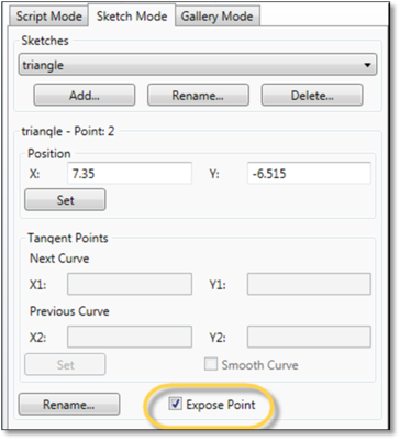
Save the file into the local "My Documents"-> "Zemax"-> "Objects"->"Part Designer Objects" folder. The final part should appear identical to the resulting part from Step II.
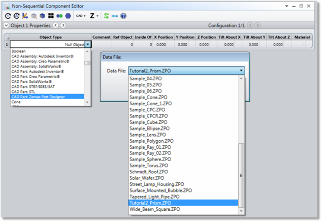
Load the part into a Non-Sequnetial Component Editor as a CAD Part: Zemax Part Designer.
Upon opening the file, the Non-sequential Editor should expose the x, y coordinates of the 2 selected points. Each value is represented by 1 Parameter within the Editor, so a total of 4 variables should appear.
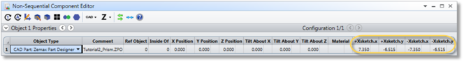
The exposed points will appear in the non-sequential mode editor as highlighted. In this case, the points were renamed to "+Xsketch" and "-Xsketch"
As the triangular cross section of the prism is symmetrical, add a pick up solve to parameter 3 (-Xsketch.x), scaling the parameter to be of the opposite sign from "+Xsketch.x" at all times. Adjusting parameter 2 will now result in an equal and opposite change for Parameter 3.
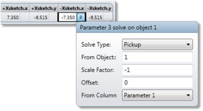
Add a pickup solve to parameter 3 to ensure that OpticStudio will adjust the points symmetrically.
The y coordinates of these control points can be ignored as they will remain fixed. Finally, Parameter 1 (+Xsketch.x) must now be made into a variable to be used for optimization.
Parameter 1 can now be used as a variable within various merit function parameters and optimization.
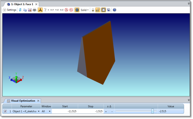
Using the Visual Optimizer slider to adjust the shape of the Prism
To increase the stability of the part, users need to add Merit Function parameters to limit the range of values a point can take. This ensures that only physical and valid parts are created.
Next: