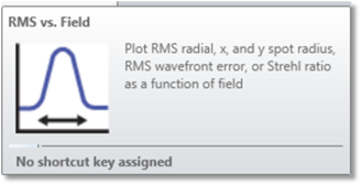
Plots RMS radial, x, and y spot radius, RMS wavefront error, or Strehl ratio as a function of field angle.
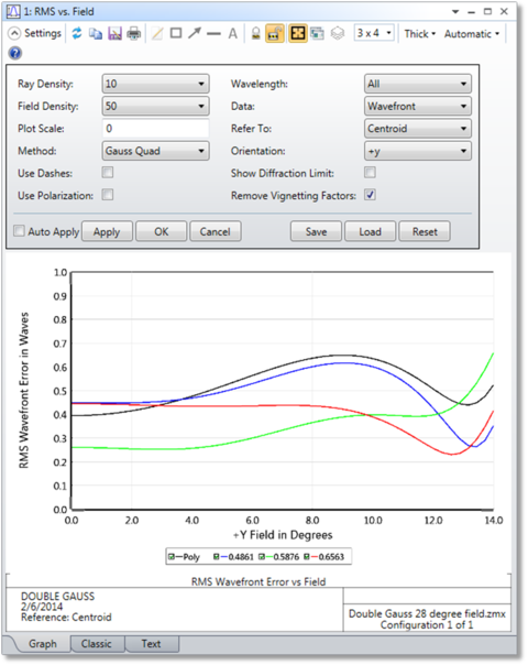
Ray Density If the method is Gaussian quadrature, then the ray density specifies the number of radial rays to be traced. The more rays traced, the greater the accuracy, although the computation time increases. The maximum number is 20 which is sufficient for pupil aberrations up to order 40. If the method is rectangular array, then the ray density indicates the grid size. Rays outside the circular entrance pupil are ignored. See the "Discussion" section for details.
Field Density The field density is the number of points between zero degrees and the maximum field angle specified at which the RMS/Strehl ratio is calculated, intermediate values are interpolated. A maximum of 100 field points is allowed.
Plot Scale Sets the maximum vertical scale for the plot. Zero results in automatic scaling.
Method Select either Gaussian Quadrature (GQ) or Rectangular Array (RA). See "Comments about RMS computation methods".
Data Selects either wavefront error, spot radius, spot x-direction, spot y-direction, or Strehl ratio. Strehl ratio is only available for monochromatic calculations, and is computed using the method described in "Strehl ratio approximation" on page 206. For a polychromatic Strehl, see the "Huygens PSF".
Refer To Select either chief ray or centroid. For monochromatic calculations, the specified wavelength is used for reference. For polychromatic calculations, the primary wavelength is used for reference. Both reference points subtract out wavefront piston. The centroid reference mode also subtracts out the tilt of the wavefront, which yields smaller RMS values.
Orientation Select +y, -y, +x, or -x field direction. Note the data will only be computed to the limits of the defined fields in the selected direction.
Use Dashes Selects either solid lines or dashed lines to differentiate the various curves.
Wavelength Select "All" to display data for each wavelength and a polychromatic computation, any one wavelength to display monochromatic data, "Poly Only" which only displays the polychromatic data, or "All With No Poly" to display all monochromatic data without the polychromatic data. Strehl ratio can only be computed for a single wavelength.
Show Diffraction Limit If checked, then a horizontal line indicating the diffraction limited response will be drawn on the plot. For RMS radius, x, or y; the diffraction limit is assumed to be 1.22 times the working F/# on axis times the wavelength (primary wavelength if polychromatic). The change in the diffraction limit due to changes in F/# with field are ignored; a single value is used across the range of the plot. For Strehl ratio, 0.8 is used, and for RMS wavefront, 0.072 waves is used. These are all approximate indicators for convenience only; the actual meaning of "diffraction limited" may be open to interpretation.
Use Polarization If checked, polarization is considered. See " Polarization (system explorer)" for information on defining the polarization state and how polarization is used by analysis features.
Remove Vignetting Factors If checked, vignetting factors are automatically removed. See "Comment about vignetting factors".
Discussion
This feature calculates the RMS error or Strehl ratio as a function of field angle for each wavelength.
Comments about RMS computation methods
Two different methods of calculation are available; either Gaussian Quadrature (GQ), or Rectangular Array (RA). For GQ, the rays traced are arranged in a radial pattern with an optimal weighting to estimate the RMS with a minimum number of rays. The method is described in G. W. Forbes, "Optical system assessment for design: numerical ray tracing in the Gaussian pupil", J. Opt. Soc. Am. A, Vol. 5, No. 11, p1943 (1988). Although the method is very efficient, the algorithm is not accurate if some of the rays are clipped due to surface apertures. To compute the RMS wavefront in systems with surface apertures requires the use of the RA method, and a larger number of rays for sufficient accuracy. For more information see "Selecting the pupil integration method".
Comments about RMS wavefront computations
For RMS wavefront computations, OpticStudio always subtracts out a reference sphere.
When referenced to the centroid, OpticStudio computes a mean shifted, tilted reference sphere. RMS wavefront error with the mean subtracted is computed as follows:
where Wn is the OPD at a given point in the pupil and wn is the weighting at that point in the pupil.
The correction method is described in M. Rimmer, "Analysis of Perturbed Lens Systems", Applied Optics Vol. 9, No. 3, p533 (1970). The raw, uncorrected OPD values do not account for the possible shift in image centroid location due to any coma that may be present. So this method is more accurate than the RMS wavefront computations when reference to Chief Ray. This same method is used when computing RMS wavefront referenced to the centroid by the default merit function.
When reference to Chief Ray, the reference sphere is a sphere centered on the chief ray - image surface intercept point.
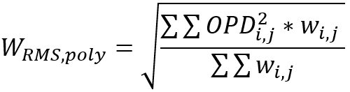
If a polychromatic computation is done, the RMS polychromatic is done for all wavelengths at the same time and for all the pupil.The RMS polychromatic is computed as follows:where
OPDi,j is the Optical Path Difference of each ray at each wavelength. The OPD value will be a different value depending on the Reference (Centroid, Chief Ray).
wi,j is the weight of each ray at each wavelength
i is the indexing of the field and pupil position of each ray
j is the indexing of the wavelength used to trace each ray
Again, this same method is used when computing RMS wavefront "Ignore Lateral Color" unticked by the default merit function, as all wavelengths will refer to the reference sphere generated for the primary wavelength.


 where
where