


Polarization Pupil Map

Generates a graph of the polarization ellipse as a function of pupil position. This aids in visualizing the change in polarization over the pupil. This feature may also be used to compute transmission in systems modeled using interfering paths in separate configurations, such as birefringent polarizing beam splitters and interferometers.
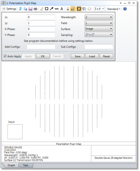
Jx, Jy Jones electric field. See "Defining the Initial Polarization"
X, Y Phase Phase of the X, Y component of the Jones electric field in degrees.
Wavelength The wavelength number of the rays to trace.
Field The field position number of the rays to trace.
SurfaceThe surface at which the data is shown. Data is after refraction through the specified surface.
Sampling The grid size of the sampling in the pupil.
Add Configs
Sub Configs If the "Add Configs" and "Sub Configs" settings are left blank, the polarization ellipse and transmission is computed for a single configuration (selected in the drop-down menu at the top of the window; "Current" is the default setting) and no interference effects are considered. To model interference between configurations see the discussion below.
Discussion
The Polarization Pupil Map has 2 tabs: Graph and Text.
The Graph tab shows the polarization ellipse. This is the figure traced out by the electric field vector as the wave propagates during one cycle. The magnitude of the ellipse is determined by the transmission of the ray which is generally a function of pupil position. For more information on analyzing polarization, see Polarization Analysis.
The transmission value is displayed at the bottom of the analysis window. This is the transmission of the polarized beam for the field, wavelength, and surface that are selected in the settings. This transmission value takes into account Ez. For each ray of the beam the intensity is calculated as Ex^2+Ey^2+Ez^2, and the transmission is displayed as the average of the intensities.
The Text tab shows the data computed by this analysis. It lists the Px, Py, Ex, Ey, Intensity, Phase, and Orientation values.
- Px and Py are the normalized pupil x and y coordinates.
- Ex and Ey are here the electric field magnitude x and y components.Ex and Ey are both complex.Ex = Exr + i Exi where Exr is the real part of Ex and Exi is the imaginary part of ExThe value listed here is the magnitude of the amplitude, or sqrt(E*E).Ex amplitude = sqrt(Exr^2+Exi^2)Ey amplitude = sqrt(Eyr^2+Eyi^2)
- The electric field intensity is calculated as Ex^2 + Ey^2. It assumes that Ez=0!
- The phase is the phase difference between the Ex and Ey phase in degrees.Note that if the X or Y component of the electric field is 0, the phase is always 0 for that component; this affects the reported phase difference between Ex and Ey.
- The orientation angle of the major axis of the polarization ellipse in degrees.
WARNING: The polarization pupil map assumes the rays are close to parallel to the z-axis and only uses the Ex and Ey components of the electric field to calculate the polarization ellipse. If the rays have a significant angle relative to the z-axis, this approximation will be invalid.
Modeling Interference Between Configurations
Some optical systems require more than one configuration to model the complete optical beam. The most common example is a polarizing beamsplitter that uses uniaxial crystals to separate orthogonal polarizations of the incident electric field. Typically, these beamsplitters implement 2 crystals with orthogonal axis orientations,
Each requiring an ordinary and an extraordinary ray trace configuration, and therefore these systems require a total of 4 configurations to model all possible ray paths.
Computing transmission through these systems can be complicated. If a single incident ray is decomposed into 4 individual rays, one for each configuration, each ray will carry a portion of the electric field and energy. It is a fundamental property of rays that the ray trace does not depend upon other rays in other configurations. Thus, if each ray is propagated individually, each will carry some portion of the electric field. If in two or more configurations the ray paths are superimposed, then the coherent sum of the individual ray paths must be considered.
Because the phase is accounted for, some rays will constructively interfere with other rays while other rays will destructively interfere. This allows OpticStudio to simulate effects such as fringes in interferometers (shearing or otherwise) or interference from various orders of a diffraction grating. However, computing the coherent irradiance involves some assumptions. Physically, destructive interference means the energy would have propagated somewhere other than where the ray went. In a similar way, when constructive interference occurs, the squaring of the amplitude sum of many rays artificially and non-physically increases the energy in the beam. OpticStudio cannot determine where the energy went (or came from), and therefore cannot account for conservation of energy in coherent irradiance calculations without making assumptions.
For the Polarization Pupil Map, the coherent irradiance for each polarization component is computed by summing the real and imaginary parts of that component for every ray, computing the square of the magnitude of this sum, dividing by the square of the sum of the coherent amplitude of that polarization component for all incident rays upon that pixel, then finally multiplying this ratio by the incoherent irradiance in that polarization component. This method allows the computed coherent irradiance to vary between a value of zero and the incoherent irradiance. However, there is no way to accurately determine the true coherent irradiance in this case because of the limitation of the ray model in the presence of constructive and destructive interference as described above. Specifically, it is unknowable where energy lost in this computation would have propagated.
To address this difficulty, the "Add Configs" and "Sub Configs" allow user specification of which configurations should be coherently summed. The "Add" configurations are all ray traced, and the electric fields are coherently summed. The "Sub" configurations are also all ray traced, and these are separately coherently summed. As part of the coherent sum, OpticStudio can determine how much energy was lost due to destructive interference between the rays in the "Sub" configurations. This energy is then added to the "Add" configurations, and the total transmission is then determined. To list multiple configurations, separate the configuration numbers with a blank space. For example, to define configurations 1 and 2 as the "Add" configurations enter "1 2".
This feature is particularly useful for analysis of birefringent systems, where two or more configurations (ordinary and extraordinary) are required to trace all possible beam paths. The computations may be applicable to other systems as well, but great care should be taken before any computed results are trusted. This feature may yield meaningless or misleading results if the "Add" and "Sub" configurations are defined in a way that does not reflect how the beams actually interfere with one another.
In addition to coherently adding multiple configurations, birefringent systems also give the user the option of tracing rays through the system using the ordinary or extraordinary index to calculate the ray's direction, then accounting for the phase difference between the ordinary and extraordinary ray. This feature is useful for waveplates and other systems where the ordinary and extraordinary beams largely overlap. See the discussion in Birefringent In for more details.
Next: