


Light Source Analysis
This feature is only available in the Premium and Enterprise editions of Ansys Zemax OpticStudio.
This feature creates an image based upon ray tracing a list of rays as the source. The rays are defined by either a DAT or a SDF Source File (only binary format ray files are supported), as used by the NSC Source File object described in Source File.
This feature is based strictly upon geometrical ray tracing. See the discussion for details.
Input The name of the DAT, SDF, or TM25RAY source file. For a complete description of this file format see "Source File".
Surface The surface at which to evaluate the rays.
Wavelength The wavelength used to trace the rays for DAT files. The rays may either be monochromatic, or may be based upon the defined wavelengths and weighting. If a SDF or TM25RAY file is used, the wavelengths specified in the file are always used, regardless of the system wavelength settings.
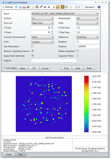
Show As Choose Grey Scale or False Color for the intensity display. If Lumens are selected for the units, then True Color is also a supported option.
Field The field position to place the source coordinate system at. It is the object point location on the object surface that define the origin of the rays in the DAT, SDF, or TM25RAY input file.
X/Y Pixels The number of pixels across the X/Y direction on the detector.
X/Y Pixel Size The size in lens units of each detector pixel measured in the X/Y direction.
Contrast Enhancement By default, no scaling of the data is done. If Contrast Enhancement, a non-linear weighting function is applied to the pixel data to exaggerate the less intense pixels. This can be useful to bring out fine detail in the image, however, the visual appearance may be misleading since dim regions will be brighter in the image than they would really be.
Reference This control defines the origin of the detector on the selected analysis surface. Either the chief ray at the primary wavelength for the selected field, or the surface vertex may be used to define the center of the detector.
Rotation This control rotates the entire source ray list about the +Z axis prior to tracing the rays. The angle is in degrees, and the rotation is counterclockwise in the XY plane.
Units Choose either Watts for radiometric analysis, or Lumens for photometric analysis. Note True Color display (for Show As) is only supported when using Lumens as the units.
Fraction Only that fraction of rays from the file will be traced. If the fraction is less than 1.0, the rays which are traced from the file are randomly selected, though for a given fraction the randomly selected rays will be identical from one analysis to the next. This feature is useful for tracing a smaller number of rays than is defined in the file.
Use Polarization If checked, polarization ray tracing will be used to consider transmission. Because no polarization data is stored in the source ray file, the polarization will be assigned randomly.
Delete Vignetted If checked, rays are not drawn if they will be vignetted by any surface.
Suppress Frame If checked, the frame is not drawn and the entire window is used to display the image.
Remove Vignetting Factors If checked, vignetting factors are automatically removed. See "Comment about vignetting factors".
Apply Fixed Apertures If checked, all surfaces with optical power that have no aperture defined are modified to have a circular aperture at the current clear semi-diameter or semi-diameter value. Without this change in the aperture definition, rays may pass the surface beyond the listed clear semi-diameter or semi-diameter, especially if the Field Y Size exceeds the field of view defined by the field points. This leads to misleading illumination, typically at the edges of the image.
Output The name of the BMP, JPG, or PNG file to write the detected bitmap to. The detected bitmap size is determined by the number of x and y pixels defined; but the pixels size must be the same in x and y for the aspect ratio to be correct in the output bitmap file. The file name must end in a BMP, JPG, or PNG extension, with no path name supplied. This file will be created or overwritten without warning and will be placed in the <images> folder (see " Folders ").
Discussion
This feature traces rays representing a complex light source through a sequential optical system. The light source is modeled using either a flux-only DAT file, a full spectrum SDF file or TM25RAY file, as described in the NSC Chapter under "Source File". Only binary format ray files are supported.
NSC Source Files may contain rays that start at any arbitrary point in space, and may travel in any direction, and be defined at any wavelength. This generality is not fully supported in the sequential ray tracing paradigm, so a few assumptions are needed.
First, the specified field point on the object surface is assumed to be the origin for all rays in the ray file, with the +Z axis of the source coordinate system parallel to the +Z axis of the object surface. The source rays may be rotated about this origin using the Rotation angle setting. Because the source rays may have a starting Z coordinate that is not zero, rays may start either behind or in front of the actual object surface. It is assumed that the first surface is far enough away from the object surface so that no rays start inside of the first or subsequent sequential surfaces.
Second, rays that travel toward the optical system may be traced beyond the limits of the entrance pupil. As long as the ray is traceable, the ray will continue through the sequential system, even if the ray is beyond the normal acceptance region of the entrance pupil. This is why it is important to use the "Apply Fixed Apertures" feature; otherwise, rays that can be traced beyond the sequentially determined aperture size may be traced all the way to the detector.
Use the "Escape" key to terminate a lengthy image analysis computation.
Next: