


Annotating 3D Layouts
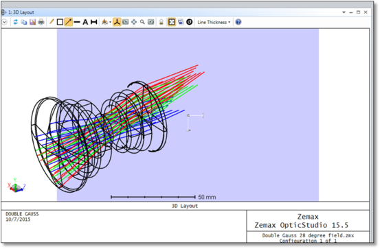
It is a little trickier to define annotations for 3D layout windows (3D Viewer, Shaded Model, etc.) since their exact position and orientation in three dimensional space must be specified. In order to unambiguously define the annotations, a temporary cutting plane is inserted in the view when adding a new annotation. This cutting plane is initially oriented perpendicular to the current camera view, but can be moved and rotated in any arbitrary way (the annotation plane is light-blue):
When setting the annotation plane position and orientation, it can be helpful to rotate the view such that it is no longer perpendicular to the annotation plane:
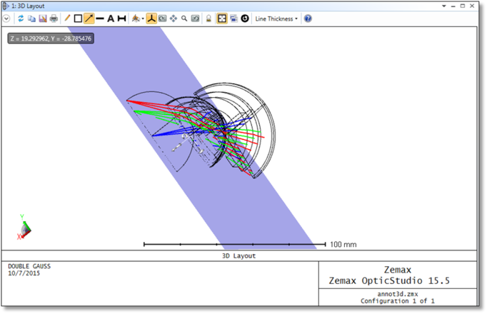
The double-sided arrow widgets at the center of the annotation plane translate the plane along its axes, while the circular arrow widget can be used to rotate the plane around the associated axis. In both cases, to manipulate the plane, left-click on the widget, and hold the button down while moving the mouse left and right. There are also several built-in mouse behaviors while annotation mode is active:
- A single right-click anywhere on the annotation will re-center the view on that point, and orient the camera perpendicular to the annotation plane.
- Shift-right-click and drag the mouse left/right to control the depth of the annotation plane (i.e. translates the plane along its normal).
- Ctrl-right-click and drag the mouse left/right to rotate the view clockwise/counter-clockwise.
- Ctrl-shift-right-click and move the mouse up/down/left/right to freely rotate the view (identical to the default Rotate behavior).
The annotation plane will stay active as long as one of the annotation modes is selected (Box, Arrow, Line, Text, or Measure). To exit annotation mode, either click on the active annotation mode icon, hit the 'Escape' key, or click on one of the camera mode icons (e.g. Rotate, Pan, etc.).
All of the 2D annotations defined above have a 3D counterpart; while the format of the annotation is similar, there are several additional parameters required:
TEXT3D "string" x y z ux uy uz rx ry rz angle scale color
The TEXT3D command will write any text within the double quotes at the location specified by x, y, and z. The orientation is defined by ux, uy, and uz (up vector), rx, ry, and rz (right vector), and the angle parameter. Scale defines the size of the text, while color defines the font color; the available colors are the same as described by the TEXT command above. Angle, scale, and color values may all be left undefined, in which case default values will be used. Note that the units, coordinate system, and color parameters are the same for all commands.
LINE3D x1 y1 z1 x2 y2 z2 color
The LINE3D command draws a straight line from x1, y1, z1 to x2, y2, z2.
ARROW3D x1 y1 z1 x2 y2 z2 vx vy vz size color
The ARROW3D command draws a one-headed arrow pointing from x1, y1, z1 to x2, y2, z2. The arrow head is drawn in a plane perpendicular to the vector defined by vx, vy, and vz. If size is 1.0 or is omitted, the arrow head is drawn at the default size. To scale the default arrow head size, use any other floating point value for size. For example, a size value of 2.0 will make the head twice as large as the default, a value of 0.5 will make it half the default size, etc.
BOX3D tlx tly tlz trx try trz blx bly blz color
The BOX3D command draws a rectangle with a top-left corner at tlx, tly, tlz, a top-right corner at trx, try, trz, and bottom-left corner at blx, bly, blz.
MEASURE3D x1 y1 z1 x2 y2 z2 vx vy vz scale color
The MEASURE3D command draws a measurement line from x1, y1, z1, to x2, y2, z2, and displays the line length in system units. The text and tick marks are defined in a plane perpendicular to vx, vy, and vz. The text size is defined by scale; doubling the scale parameter will roughly double the size of the measurement text.
Next: