


Surface Sag
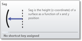
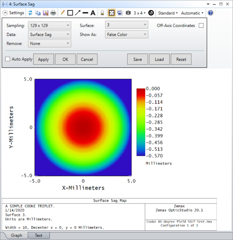
Displays the sag of a surface as a 2D color or contour map, or as a 3D surface plot.
Sampling The size of the grid used. The sampling may be 33x33, 65x65, etc.
Contour Format The contour format string. For a discussion of the contour format string syntax, see "The Contour Format String" below. The contours are defined in lens units.
Surface The surface number at which the sag will be computed and displayed.
Data Choose Surface Sag.
Show As Choose surface plot, contour map, grey scale, or false color map as the display option.
Off-Axis Coordinates When checked, the plot will consider any apertures defined in the Surface Properties of the surface. The coordinate system for the sag computation will have an origin at the vertex of the off-axis part.
Valid apertures for this option will be: Circular Aperture, Rectangular Aperture, Elliptical Aperture, User Aperture, and Floating Aperture.
This option does not support surfaces that have tilt terms at the vertex of the surface, such as Tilted surface types.
Remove The Remove selection gives the option to remove "None", "Base Radius", "Best Fit Sphere", "Base Sag" or "Composite Sag".
If "Base Radius" is selected, the base radius of curvature of the surface will be subtracted from the current sag, and the difference will be reported.
If "Best Fit Sphere" is selected another option will appear labelled "Criterion" The Criterion section will explain the options for Remove Bet Fit Sphere.
If "Base Sag" is selected, the analysis displays:
- in case STAR data is applied to the surface, the sag difference between the surface with STAR effects applied and the original surface. This is useful to visualize small changes in sag due to the FEA data.
- in case the surface is a Composite Base or Add-on, the sum of sag profiles of any composite Add-on surfaces up to and including the surface above the one considered. This is useful to visualize Composite Add-on profiles that are added to the Composite Base.
If "Composite Sag" is selected, the analysis displays the sag profile of the surface being considered, ignoring any Composite Add-on surfaces added to it.
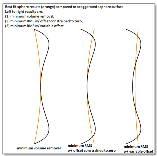
Criterion The Criterion selection appears when Remove Best Fit Sphere is selected and gives the option to select "Minimum Volume", "RMS, no offset", "RMS, with offset". When "Minimum Volume" is selected, a new checkbox labelled "Reverse Direction" will appear. Reverse direction changes the sign on the radius of curvature of the best-fit sphere. This results in fitting, for example, a concave best fit sphere instead of a convex best fit sphere. These selections indicate where the Best Fit Sphere will be subtracted from the surface.
The diagram below shows this more clearly:
Discussion:This feature accounts for the size and shape of any aperture present on the surface; even if the aperture is decentered. The sag is computed on a uniform grid of points in XY plane, and the Z value of the sag is the displayed data.
See also the Surface Phase feature described below.
The Contour Format String
The Contour Format string allows some control over the appearance of the contour map.
If left blank, the default contour spacing will be selected. If a single value is entered, then the contour spacing will be set to this value. For example, if 0.05 is entered, the contour interval will be 0.05. If multiple values separated by spaces are entered, only those contours will be drawn. For example, if "0.8 0.5 0.2" is entered, only those three contours will be drawn. If the specified contour settings result in too many contours to be drawn properly, the default number of contours will be selected.
Next: