


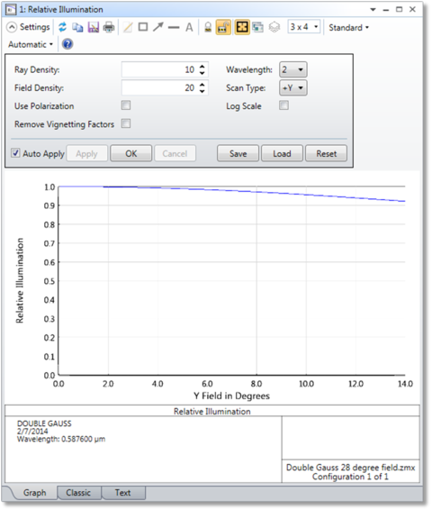
Relative Illumination
The Relative Illumination analysis computes the relative illumination as a function of radial field coordinate for a uniform Lambertian scene. This feature also computes the Effective F/#.
Ray Density The number of Rays on one side of an array of rays used to integrate the illumination of the exit pupil. A value of 10 will trace about 10 x 10 x pi / 4 or 78 rays. Higher ray densities yield more accurate results at the expense of longer computation times. The Ray Density minimum value is 5.
Field Density The number of points along the radial field coordinate to compute the relative illumination for. Larger field densities yield smoother curves.
Use Polarization If checked, polarization is considered. See " Polarization (system explorer) " for information on defining the polarization state and how polarization is used by analysis features.
Remove Vignetting Factors If checked, vignetting factors are automatically removed. See "Comment about vignetting factors" in the description of "FFT MTF vs. Field".
Wavelength Selects the wavelength for computation. Relative illumination is a monochromatic entity.
Scan Type Choose +y, +x, -y, or -x field scan direction.
Log Scale If checked, a logarithmic rather than linear scale will be shown.
Discussion
This feature computes the relative illumination (RI) as a function of radial y field coordinate. RI is defined as the intensity of illumination per unit area of image surface normalized to the illumination at the point in the field that has maximum illumination (which may not be on axis). The computation considers apodization, vignetting, apertures, aberrations of both the image and pupil, variations in F/#, chromatic aberrations, image surface shape, angle of incidence, and optionally, polarization effects assuming unpolarized light. The method is based upon one described in M. Rimmer, "Relative illumination calculations", Proc. SPIE Vol. 655, p99 (1986). The published method was extended to include apodization, transmission, polarization, and non-planar image surface effects. The computation method assumes the following are all true:
- The object scene is plane, uniform, and Lambertian.
- The image surface is a reasonably good conjugate (that is, an image) of the object surface, so that rays coming from small patches of light on the object surface are imaged to patches of light on the image surface. Aberrations are fine, but the rays should be reasonably localized on the image surface.
- The exit pupil is not too close to the image surface. This condition will be satisfied if the F/# is larger than about 0.1 and the ray aberrations are small compared to the exit pupil distance.
- The cosine space aberrations are not so severe as to form caustics in angle space. A caustic in angle space means that rays in different parts of the entrance pupil have the same angle in image space. To check this, use the "Direction Cosines" option on the spot diagram feature (See the "Standard Spot Diagram" analysis).
The relative illumination is computed by integration of the effective area of the exit pupil as seen from the image point(s). The integration is carried out in direction cosine space using a uniform grid in image cosine space.
Note that the RI computation will not in general yield a cosine-fourth curve, because the so-called cosine-fourth "law" is actually an approximation based upon a thin, slow, aberration free lens with the stop at the lens. For more general lenses, including telecentric, aberrated, or vignetted lenses, the RI can be computed using an integration of the projected solid angle or effective area of the exit pupil as seen from the image location, and this computation will not yield a simple cosine-fourth curve. If a system violates the assumptions of the computation an error message will be displayed and the RI will not be computed.
Effective F/#
The text listing of the relative illumination data also includes data for the Effective F/#. The Effective F/# is the F/# required for a perfect optical system with 100% transmission and a circular exit pupil to have the same image illumination as the system being evaluated. The Effective F/# is computed by:

where A is the area of the projected solid angle of the pupil in cosine space weighted for system transmission. The Effective F/# is a useful metric for comparing the brightness of the image formed by different optical systems, because it accounts for RI and is independent of the aperture shape. For more information, see "F-Number and the radiometry of image forming optical systems with non-circular aperture stops," R. Siew, Proc. of SPIE Vol. 5867 (2005).
Next: