


Rectangular Volume
There are 9 parameters used to define the rectangular volume:
| Parameter # | Description | Face Name | Face # |
| 1 | The X half width of the front face. | Front | 1 |
| 2 | The Y half width of the front face. | Front | 1 |
| 3 | The Z length of the volume along the local Z axis. | Side | 0 |
| 4 | The X half width of the rear face. | Back | 2 |
| 5 | The Y half width of the rear face. | Back | 2 |
| 6 | The front face tilt angle in degrees along X. | Front | 1 |
| 7 | The front face tilt angle in degrees along Y. | Front | 1 |
| 8 | The rear face tilt angle in degrees along X. | Back | 2 |
| 9 | The rear face tilt angle in degrees along Y. | Back | 2 |
Rectangular volumes are usually 6 sided solids. However, shapes such as pyramids and wedges may be created by setting one or more of the parameters to zero.
When performing Boolean operations with rectangular volumes, or exporting rectangular volumes in CAD format, any face with a width of less than the export tolerance will be removed.
The reference point is the center of the front face. Face Numbers: Front face Face 1, back face Face 2, all other faces Face 0.
Comment about tilted faces
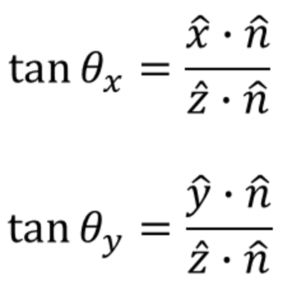
The tilt of the front and rear faces is performed as follow:
where θx and θy are tilt angles X and Y, n is the normal vector of the front or rear face, x, y, z are the unit vectors of local XYZ axes of the Rectangular Volume object.
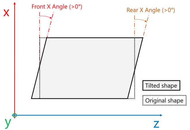
In OpticStudio, the parameters 6 and 8, Front X Angle and Rear X angle, respectively tilt the surface about the Y axis resulting in an angle between the X axis and the surface. The parameters 7 and 9, Front Y Angle and Rear Y angle, respectively tilt the surface about the X axis resulting in an angle between the Y axis and the surface. The pivot point for the tilts is at the surface vertex, as depicted in the scheme below.
Note that if the front and rear face X half widths are not the same, and there is a tilt along the Y direction on either the front or rear face, then the four corners on the sides of the "box" are no longer coplanar. This yields an odd shape that OpticStudio models as two triangles, with a crease along the diagonal. A similar condition occurs if the front and rear Y half widths are different and a tilt along X is defined on either face. Although no error message is issued in these cases, the resulting object model should be carefully studied to confirm the desired shape is generated.
Next: