


Huygens PSF

Computes the diffraction PSF using direct integration of Huygens wavelets method. The Strehl ratio is also computed.
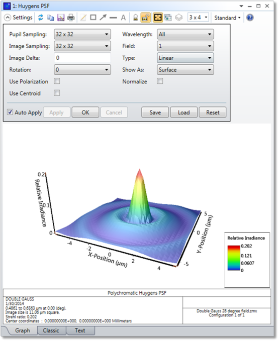
Pupil Sampling Selects the size of the grid of rays to trace to perform the computation. Higher sampling densities yield more accurate results at the expense of longer computation times.
Image Sampling The size of the grid of points on which to compute the diffraction image intensity. This number, combined with the image delta, determine the size of the area displayed.
Image Delta The distance in micrometers between points in the image grid. Use zero for the default grid spacing.
Rotation Rotation specifies how the surface plots are rotated; either 0, 90, 180, or 270 degrees.
Wavelength The wavelength number to be used in the calculation.
Field The field number for which the calculation should be performed.
Type Select linear (intensity), or logarithmic (intensity). The logarithmic scaling can range from 1 to 5 decades. Also available are real amplitude, imaginary amplitude, and phase in degrees. For more context on the relationship between linear and complex amplitude, see the discussion section below.
Configuration Select "All" to perform a coherent sum of the PSF at each wavelength across all configurations, or select the "Current" or any single configuration. Note this is a coherent sum for the same wavelength in each configuration, followed by an incoherent sum of the resulting PSF's for different wavelengths. For this reason, each defined wavelength must be the same in all configurations. Wavelength and configuration weights may be used but the wavelength values must be identical. See CWGT and WLWT in "Summary of multi-configuration operands". This coherent sum also assumes that the image surface is located in the identical position in all configurations. If "All" is selected, and both focal and afocal mode configurations are defined, the Configuration setting will automatically be reset to "Current".
Normalize If checked, the peak intensity will be normalized to unity. Otherwise, the peak intensity is normalized to the peak of the unaberrated PSF (the Strehl ratio).
Show As Choose surface plot, contour map, grey scale, or false color map as the display option. The True Color option creates an RGB color representation of the PSF by converting the wavelengths to the closest RGB equivalent and summing over all wavelengths. The accuracy of the True Color presentation is limited by the RGB method of rendering color on a computer display; and it is not possible to exactly represent monochromatic colors. The True Color option cannot be used if the Type is anything other than linear. Note that choosing True Color will require a recalculation of the data, as it is computed by a separate method. Choosing between the other display options does not require a recalculation.
Use Polarization If checked, polarization is considered. See " Polarization (system explorer) " for information on defining the polarization state and how polarization is used by analysis features.
Use Centroid If checked, the plot will be centered on the geometric image centroid. If unchecked, the plot will be centered on the chief ray.
Discussion
One way of considering the effects of diffraction is to imagine each point on a wavefront as a perfect point source with an amplitude and phase. Each of these point sources radiates a spherical "wavelet", sometimes called a "Huygens wavelet" after Huygens, who first proposed the model. The diffraction of the wavefront as it propagates through space is given by the interference, or complex sum, of all the spherical wavelets radiated.
To compute the Huygens PSF, a grid of rays is launched through the optical system, and each ray represents a particular amplitude and phase wavelet. The diffraction intensity at any point on the image surface is the complex sum of all these wavelets, squared. The PSF is computed this way for every point on the image grid. The center coordinates, reported both in the graph and in the text listing, are defined by the geometric centroid of the beam if "Use Centroid" is selected, while they correspond to the chief ray of the field point for which the PSF has been calculated if "Use Centroid" is not selected. The graph is always centered on these center coordinates, i.e. the coordinate (n/2+1), (n/2+1), where n is the number of points in the image space grid. The data output for a rotationally symmetric system will be symmetric about the point (n/2, n/2+1). Besides, regardless of whether "Use Centroid" is selected or not, OpticStudio always calculates the shift between the center coordinates and the centroid of the Huygens PSF itself, which is determined from the second moment analysis of the PSF. This shift is reported as the centroid offset in the text listing. Then, the sum of the center coordinates and the centroid offset is reported as the centroid coordinates in the text listing.
The Image Delta value determines the point spacing of the image space grid. If a value of zero is specified, a default grid spacing is used. The default Image Delta is given by:

where np is the number of points in the pupil space grid, λ is the selected wavelength in the settings, and F is the working F/#. If the Wavelength settings is All, then λ is the longest of the defined wavelengths. The exact value of the image Delta size is not critical, as long as the entire width of the PSF is included within the range of n * (Image Delta).
Unlike the FFT PSF, OpticStudio computes the Huygens PSF on an imaginary plane tangent to the image surface at the chief ray intercept. Note the imaginary plane is normal to the normal of the surface, not the chief ray. Therefore, the Huygens PSF accounts for any local tilt in the image surface caused by either the image surface slope, the chief ray incidence angle, or both.
The Huygens method accounts for the evolving shape of the diffraction image as the beam propagates along the image surface. This is an important effect if the image surface is tilted with respect to the incoming beam. Another advantage to the Huygens PSF method is that any grid size and spacing may be selected by the user. This allows direct comparison between PSF's from two different lenses, even if the F/#'s or wavelengths are different.
The only disadvantage of the Huygens PSF is speed. Direct integration is slow when compared to the FFT method (see the previous section for details). The computation time depends upon the pupil grid size squared times the image grid size squared, times the number of wavelengths. OpticStudio accounts for any symmetry the system has. The Huygens PSF automatically uses all available processors for maximum speed on multiple CPU computers.
In general, a planar reference is used to calculate the phase when constructing the Huygens PSF. This reference works well when the rays can be assumed to come from a distant pupil, and when the size of the image region we are interested in is small. This allows every ray coming from the pupil to be treated as a plane wave. A plane wave has constant phase over the plane, so the phase of the plane wave as it hits the center of a single pixel in the image is just the phase of the ray, plus 2p/l times the distance from plane wave to the pixel. The Huygens PSF is then provided by a coherent sum of all the plane waves, each representing a single ray.
However, if the image is large, then the distance from any given ray in the pupil to each pixel might vary enough to where the plane wave approximation cannot be used. This can be determined by computing the distance from the exit pupil to image center, and the distance from the exit pupil to corner of the image. If these two distances differ by more than l/4, the plane wave approximation will not be a good representation of the system because there will be a non-negligible amount of phase curvature of the image. In this case, OpticStudio will instead use a spherical wave for the phase reference. Doing so can increase the computation time for the Huygens PSF – because we have to compute the phase for each pixel and can no longer assume a linear relationship with pixel coordinates – but provides a much more accurate calculation of the PSF for systems with significant aberrations at the image plane (for which the plane wave reference often leads to noisy results). The occasional use of the spherical wave reference thus expands the applicability of the Huygens PSF to a wide range of systems, such as those used to model computer generated holograms.
By default, OpticStudio will use the criterion described above to automatically determine whether to use the planar or spherical phase reference in the exit pupil for the Huygens integration.
However, to override this for a system, change the selection in the System Explorer for the " Method to Compute Huygens Integral " option (see The Setup Tab > System Group > System Explorer > Advanced).
The basic relationship between the Linear PSF (Units in Flux) and then Complex Amplitude which is defined as "Real PSF + i* Imaginary PSF" and has the units of field or sqrt(flux), is given as Linear PSF = (Real PSF)^2 + (Imaginary PSF)^2. The Huygens summations for Linear, Real and Imaginary quantities are all separately accumulated, so their values may converge at slightly different rates regarding pupil and image sampling.
Please be aware that if doing a polychromatic PSF, a wavelength-based factor "wFactor" is applied to the Linear PSF type. The purpose of this factor is to weight the different wavelength contributions to the polychromatic PSF. The wFactor is given as:

While ω-multi is given by the value of the CWGT operand from the multi-configuration editor and the ω-wave is the wavelength weight from the wavelength settings.
Comments about polarization and summing PSFs across multiple configurations
If beams in different configurations are orthogonal and strongly polarized, then the input polarization must be considered for the Huygens PSF results to be accurate. The "Unpolarized" setting in System Explorer should be turned off and "Use polarization" should be turned on in the Huygens PSF properties. See " Polarization (system explorer) " for more information on the polarization settings in the System Explorer.
The Huygens PSF results may be inaccurate if "Use polarization" is checked on in the Huygens PSF settings, but "Unpolarized" is checked on in the System Explorer. If the PSF is summed over multiple configurations with these settings, OpticStudio calculates the average polarization transmission for each configuration, and assigns the resulting energy to the x component of the transmitted field. Because the resulting energy for the configurations is artificially put into this state, they will sum coherently in the Huygens PSF. However, beams with orthogonal polarization should not interfere coherently, and therefore this result will be inaccurate if beams in different configurations are orthogonal and strongly polarized. To prevent this from occurring, the "Unpolarized" setting in System Explorer should be turned off, so that the correct polarized beam input is used.
Next: