


Footprint Diagram

Displays the footprint of the beam superimposed on any surface. Used for showing the effects of vignetting and for checking surface apertures.
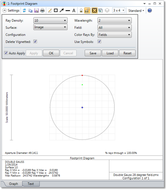
Ray Density Determines the number of rays traced across the half pupil; a setting of 10 will trace a grid of 21 x 21 rays.
The "Ring" option will trace 360 marginal rays around the edge of the pupil at each field and wavelength. The ring option will automatically determine the radial coordinate of the marginal ray that is not vignetted to approximate the shape of the beam on any surface, but will yield incorrect results if the beam is in a caustic.
Surface The surface to show the beam footprint on.
Wavelength The wavelength number to be used in the calculation.
Field The field number to be used in the calculation.
Delete Vignetted If checked, then rays which are vignetted by subsequent surfaces will not be drawn. Rays which are vignetted by prior surfaces are never drawn.
Use Symbols If checked, this option will draw different symbols rather than dots for each wavelength. This helps distinguish the various wavelengths.
Configuration Select "All" to show all configurations, "Current" to show just the active configuration, or select any combination of other configurations.
Color Rays By Select "Field #" to use color to distinguish between each field position, or "Wave #" to distinguish between each wavelength, "Config #" to distinguish between configurations, and "Wavelength" to approximate the color of wavelengths in the visible spectrum.
Discussion
This feature will draw the shape of the surface, and then superimpose on that surface a grid of rays. If there is no aperture on the surface, then a circular surface shape with a radial clear aperture of the clear semi-diameter or semi-diameter value is shown. Otherwise, the shape of the aperture is shown. The surface aperture is always shown as centered in the frame; even if the aperture is decentered on the actual surface. If there is an obscuration on the surface, then the obscuration will be drawn along with the circular aperture defined by the clear semi-diameter or semi-diameter. If the surface aperture on the selected surface is modified between different configurations, and more than one configuration is selected, the aperture for the first configuration only will be drawn.
The ray grid size is specified by the ray density parameter, and rays may be from any or all fields, at any or all wavelengths. Rays which are vignetted by surfaces prior to the surface shown are not drawn. Rays which are vignetted by the surface or subsequent surfaces are not drawn if "delete vignetted" is checked, otherwise, they are drawn. The ray set is apodized if any system pupil apodization is selected. The number of rays shown divided by the total number of rays launched is listed as the percentage of rays through if the Ray Density is not "ring".
For graphic windows, the left/right cursor keys will change the surface number and recompute the data.
Comments on percentage of rays through in Footprint Diagram and the efficiency in Geometric Image Analysis
One should be careful when comparing these two values. There are several reasons that users can find difference between the two values. The following are some possible reasons why the difference is observed.
Next: