


Dipvergence/Convergence

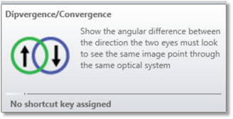
Displays the dipvergence and convergence for biocular analysis.
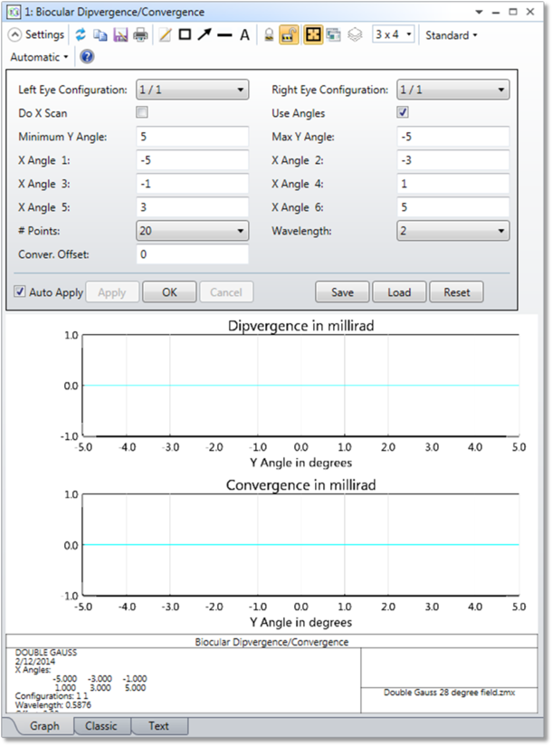
Left Eye Config Defines the configuration to use as the left reference eye.
Right Eye Config Defines the configuration to use as the right eye, whose dipvergence and convergence is determined relative to the left eye.
Do X Scan If checked, the plot scan is across the X direction field of view, otherwise, the scan is across the Y direction field of view.
Use Angles If checked, the field of view units are degrees, otherwise, the units are direction cosines.
Min/Max Angle / Cosine Sets the limits of the scan in X or Y, in either cosine space or in degrees. Note the limits do not need to be symmetric, and the min value need not be less than the max value.
X/Y Angle/Cosine 1-6 If "Do X Scan" is checked, then up to 6 Y angles/cosines offsets may be selected for display. If "Do X Scan" is unchecked, then up to 6 X angles/cosines offsets may be selected for display. To turn off one or more of the offset values, set the value to -99.
# Points The number of points to use across the full scan.
Wavelength The wavelength number to be used in the calculation.
Convergence Offset This value is subtracted from the computed convergence value. This allows only the deviation from the desired value to be displayed.
Discussion
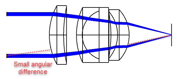
When two eyes are used to look through a biocular lens, there is usually a small angular difference between the direction the two eyes must look to see the same image point.
- The vertical (up/down) angle is called dipvergence.
- The horizontal left-right angle is called convergence or divergence.
- Convergence means the eyes gaze toward a common point in front of the viewer's head so the chief rays from the two eye positions would converge as they move toward the lens and away from the viewer's head.
- Divergence means that the two chief rays diverge as the rays propagate toward the lens, as if to see a virtual image point behind the head.
- Convergence and divergence are really the same thing from a computational standpoint. OpticStudio uses the common convention that convergence is a positive value and divergence is a negative value; for this reason only the term convergence will be used in the subsequent discussion, with the understanding that if the convergence is negative then it is properly called divergence. Usually, convergence is more tolerable than divergence and the two aberrations may have different specifications.
Dipvergence and convergence are both measured in milliradians, and typical limits are on the order of 1.0 milliradians for visual systems.
The computation proceeds for a given point in the field of view by tracing a reference ray in the left eye configuration. The same angle chief ray is then traced in the right eye configuration. In general, the right eye ray will not land on the exact same X, Y coordinates on the image surface as the left eye reference ray did. OpticStudio iterates the right eye trace until the chief ray is found that matches the left eye reference ray intercept coordinates. The resulting right eye chief ray will in general make some angle with respect to the left eye in both the vertical and horizontal directions, and it is these angles that are the dipvergence and convergence, respectively.
This feature makes all of the following assumptions:
- The field of view is either angles in degrees or in direction cosines directly.
- The image surface is assumed to be the location of the image the eyeball is looking at. Each selected configuration should represented a single (usually decentered) eyeball position.
- The eyeball decenter should be set up so that the X, Y coordinates on the image surface represent the same point on the image source in all configurations. For example, if the image source is a Cathode-Ray Tube (CRT) display, then the point with image coordinates (x = 1, y = 2) should correspond to the same physical location on the CRT in all configurations.
- All surfaces should have fixed apertures for the purposes of vignetting rays that are outside of the field of view.
Note that both the left eye and the right eye chief rays must pass all surfaces without errors and without vignetting for the computation to be valid. If both rays do not trace, no data will be returned for that field of view. The field of view overlap between the configurations is very useful for setting appropriate min/max scan values, see the "Field of View" for determining the field of view overlap.
It is possible for the iteration required for the right eye to fail. This typically happens if either no solution exists or if the dipvergence/convergence is so large that algorithm becomes unstable. Failed iteration will usually show up as gaps in the plot.
Next: