


Design Lockdown

The Design Lockdown Tool converts all idealized inputs of a system into Real Manufacturing Inputs of a production system.
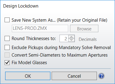
Save New System As: When checked, the Design Lockdown Tool creates the specified .ZMX file to store the production system. When unchecked the Design Lockdown tool overwrites the current system with the production system.
Round Thicknesses to: Round the thicknesses of all surfaces to the specified precision.
Exclude Pickups during Mandatory Solve Removal: When checked, the Design Lockdown Tool leaves pickup solves in place after conversion to the production system but removes all other solves. When unchecked, the Design Lockdown tool removes all solves, including pickup solves, from the production system. This option is only available for files having a single configuration. For more information about how solves are handled in files having multiple configuration, please see Discussion section below. For both single and multiple configuration files, the special cases below are applicable:
- Pickups on clear semi-diameters or semi-diameters, chip zones and mechanical semi-diameters are always set to fixed.
- Material Offset solves are never removed.
- If a Material solve picks up a model material, the pickup is removed. The surface with the solve is then changed to either a Model glass with same model parameters or to an equivalent real glass, depending on the "Fix model glasses" option. See description below.
- For systems with multiple configurations, this option is not available and is grayed out. All solves and variables will be left in place.
Fix Model Glasses: If checked, all Model glasses in the system will be replaced with the closest glass in the currently loaded catalogs. If unchecked, all Model glasses in the system will be kept in place.
Convert Semi-Diameters to Maximum Apertures: If checked, the Design Lockdown tool removes all automatic semi-diameter solves and replaces them with their maximum value across all configurations, after the steps described in the Discussion section have been performed. If un-checked, all automatic-semi diameter solves will be set to Fixed in each configuration separately, so as to keep their value unchanged. Note that this option affects all Automatic solves placed on Clear Semi-Diameters, Semi-Diameters and Mechanical Semi-Diameters. This option is only available for files having multiple configurations.
Discussion
A number of steps are generally required to take a system designed in sequential mode into a production system. In particular all idealized inputs of the system must be converted into real manufacturing inputs. The Design Lockdown Tool automates this conversion by:
- Switching to Paraxial Ray Aiming, if Ray Aiming is off.
- Converting any surface (other than coordinate breaks or ignored surfaces) with clear semi-diameter or semi-diameter = 0 to the clear semi-diameter or semi-diameter value that is calculated automatically by Zemax.
- Changing the system aperture to Float By Stop Size unless the aperture type is "Object Space NA" or "Object Cone Angle". See Aperture Adjustment Details below. This step will be skipped for systems with multiple configurations.
- Switching from the use of image-based field point definitions (if they are being used) to object-based definitions. The primary wavelength is used for this conversion.
- For finite conjugate systems, Object Height is used as the field definition.
- For infinite conjugates, Angle is used as the field definition, unless the system is already using Theodolite Angles.
- Systems with multiple configurations will not be converted to object-based field definitions; any analysis features or conversion to non-sequential should be manually verified if the sequential system is defined with image-based field definitions.
- Remove all solves if required. See the discussion in Exclude Pickups during Mandatory Solve Removal. For multiple configuration files also refer to Convert Semi-Diameters to Maximum Apertures for details. In particular for multiple configuration files:
- If the value of a cell controlled by a solve doesn't change across all configurations, the solve is simply removed.
- If the value of a cell controlled by a solve changes across configurations, the corresponding multi-configuration operand is added in the multi-configuration editor to ensure the value of the cell is consistently maintained in all configurations after running the tool.
- Any multi-configuration operand applied to a solve parameter will be removed from the multi-configuration editor.
- Replacing vignetting factors with fixed apertures.
- Removing all variables.
- Rounding thickness values if necessary.
For systems with new configurations, a few operands are not currently supported. A full list of the operands can be found here: APER, SATP, XFIE, YFIE
Aperture Adjustment Details
If the stop size is set to be larger than the stop size automatically calculated by OpticStudio, the Design Lockdown Tool will respect the original Aperture Type when converting to Float By Stop Size. For instance, it is possible to set the Aperture Type to Entrance Pupil Diameter and use a Fixed Solve on the Stop to represent a mechanical semi-diameter that is larger than the optical semi-diameter. For cases such as these, the new optical semi-diameter is set to whatever it needs to be so that the new system retains all the properties of the original, but with the aperture type switched to Float By Stop Size. For example, if the original system uses the EPD, we set the stop semi-diameter to be such that the EPD in the new system equals the EPD in the original. If the stop surface supports mechanical semi-diameters, then OpticStudio adjusts the chip zone so that the mechanical semi-diameter is set to the original optical semi-diameter.
Notes on fixing Model glasses
When replacing a Model glass with the closest glass in the loaded catalogs, it may be the case that the index of refraction or dispersion data changes significantly enough to affect overall system performance. To ensure this doesn't happen, users can take two approaches:
-
Ensure the Model glass being used is close to - if not exactly - the same as a glass within the selected Material Catalog. Preferably, this should be the glass that will be used during the manufacturing process.
-
Build a unique catalog of glasses based on the Model glass data. Note: this is not recommended for late-stage design work. When building for manufacture, users should always use the data specific to the material they intend to manufacture with instead of an idealized model.
For option 2, there are a few ways to create a user-defined catalog. A useful method is to use the INDX optimization operand to collect the index of refraction for the Model glass at at least three wavelengths. Then fit this data to the Conrady dispersion formula and generate a user-defined material within a user-defined catalog. Replace the Model glass with this new material. For more guidance on creating unique materials, see the Knowledgebase article "How to add new materials and glasses in OpticStudio".
Next: