


Combine Objects
Perform Boolean operations such as AND, OR, and XOR on any two objects.

The Combine Objects tool works by applying Boolean operations on the two selected objects to "trim" the overlapping regions to form a new single object. The new object is then exported in the selected CAD format, such as IGES or STEP. The new object may then optionally be imported for ray tracing. For more information on imported CAD objects, see " CAD Part: STEP/IGES/SAT ". When exporting in STL format, OpticStudio imports the new object using the STL object type. For a description of the STL object see " CAD Part: STL ".
The Boolean operations are performed by converting each component object into a NURBS based representation, and then a series of Boolean trimming and combining operations are performed to yield the resulting object. For this reason, Boolean CAD objects have the same considerations that imported CAD objects do; see "Comments about imported CAD objects" for a discussion. Some loss of precision is possible when converting from OpticStudio native, high precision representations to NURBS representations; this is not a limitation of OpticStudio but is inherent in the NURBS representation of arbitrary surfaces. Generally, precision can be increased as desired using the Spline and Tolerance parameters described above. When extreme optical precision is required, the user should verify that the Boolean CAD object traces to a suitable accuracy.
When the maximum possible ray trace accuracy is required, an alternative to combining objects is to create a User Defined Object. For more information, see " User Defined Object ".
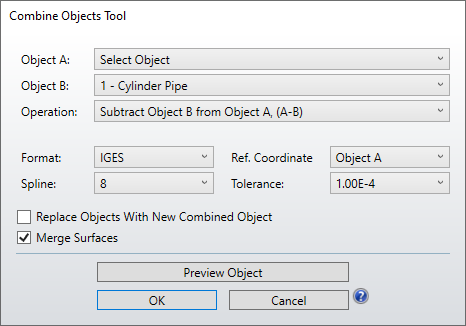
Settings:
Object A, B The first and second objects to be combined.
Operation Defines the Boolean operation to perform on the selected objects.
Intersection of objects: The region contained by both objects.
Union of objects: The region contained by either object.
Either, But not both objects: The region contained by either but not both objects.
Subtract Object B from Object A: The part of A that is not part of B.
Subtract Object A from Object B: The part of B that is not part of A.
Format The file format to use to save the resulting object.
Spline This setting defines the number of spline points to use for each aspheric face. A larger number of spline points generally produces more accurate results at the expense of larger files, slower ray tracing, and slower object creation. This setting has no effect on objects which are not aspheric.
Ref. Coordinate This setting defines the coordinate system used by the combined object. If Global is selected, the object will be position relative to the origin of the NSC system. If Object A or B is selected, then the object will be positioned relative to the local coordinate frame of Object A or B respectively.
Tolerance The dimensional tolerance in lens units. Some formats use a tolerance parameter to define the accuracy of the representation. Smaller tolerance values generally produce more accurate results at the expense of larger files, slower ray tracing, and slower object creation.
Replace Objects With New Combined Object If checked, once the object is created, the selected objects A nd B will be replaced with the newly created object. If not checked, the object will be created but will not automatically be imported to the NSC Editor.
Preview Object If pressed, this button will present a Shaded Model display of the object that would be created with the specified settings. This Shaded Model display may be rotated and zoomed to visually verify the correct shape will be created.
Next: