


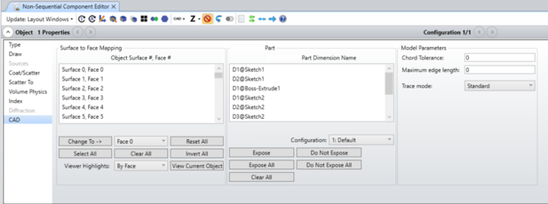
CAD
The imported CAD objects, the Source Imported, the Boolean CAD object, the Boolean Native, and the Swept object use the CAD section of the Object Properties dialog. The Object Properties can be reached by clicking the down arrow in the Object Properties bar above the NSC Editor.
Surface to Face Mapping
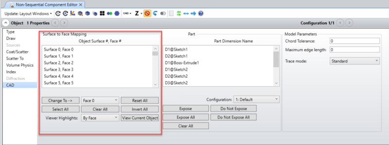
The controls in this section are used to assign face numbers to the various surfaces defined in an imported CAD format file. The face number assignments are stored in a file with the same name as the imported CAD file with the extension *.ZAN appended. For example if the original file is SlottedBlock.SLDPRT, then the file created will be SlottedBlock.SLDPRT.ZAN. The ZAN file is stored in the {Zemax}\Objects\CAD Files folder. If the object definition changes the ZAN file is automatically regenerated.
Note that when the "Use Parasolid Libraries" option is un-checked in OpticStudio Preferences > General, face number assignments are instead stored in a file may vary. This is because the number and order of the faces can be different depending on the CAD Libraries used.
The following logic is used when new ZEN/ZAN files are created:
- All new ZEN/ZAN files are created with Surface 0 through Surface 50 having Face 0 through Face 50 and then Surfaces greater than 50 are all defaulted to Face 0
-
If a ZEN exists but no ZAN, the ZEN is copied into the newly created ZAN
-
If a ZAN exists but no ZEN (when choosing to downgrade to the older CAD libraries), then the ZAN is copied into the newly created ZEN
-
If the ZEN file has the option of "Use single surface" in the Surface Mode, then when the ZAN is created, all Surfaces will be defaulted to one Face
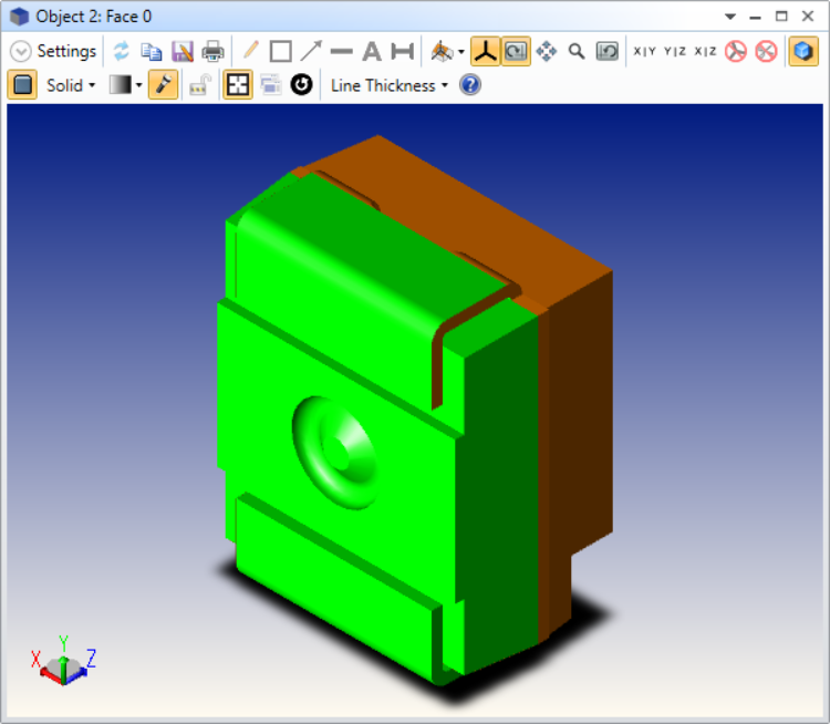
Object Surface #, Face # This control selects the desired surface number. Changing the selection in this control will update the NSC Object Viewer if the viewer is opened from the "View Object" button at the bottom of the tab. The screenshot below is of sample part "LB_T67C_190608_GEOMETRY.STEP" with Face 0 selected in the Object Viewer. Note more than one surface may be selected at one time. This allows groups of surfaces to be selected and renumbered together using the "Change To->" button. An alternate method to select surfaces is to click on the surface in the NSC Object Viewer.
Change To-> Face # Pressing "Change" will change the highlighted surface numbers to the selected Face number.
Reset All Automatically renumbers all surfaces to the default. The default is to assign each surface a unique Face number starting at 0 through the maximum number of Faces supported. All remaining surfaces are assigned Face number 0.
Select All Selects all surfaces.
Clear All Unselects all surfaces.
Invert All Reverses the selected and unselected surfaces.
Viewer Highlights Sets the NSC Object Viewer to highlight in red all selected surfaces or all selected faces. Note if multiple surfaces are assigned the same face number, then highlighting by face will show all surfaces with the same face number.
View Current Object Opens the NSC Object Viewer
To change how OpticStudio initially determines the number of unique surfaces and sets the default face numbering, see "CAD Part: STEP/IGES/SAT". If the object is a Autodesk Inventor part or Creo Parametric part, this is also where the associated controls are found.
Model Parameters
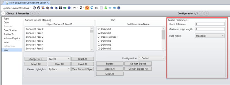
Chord Tolerance: This setting affects the rendering of the object. It performs a very similar function to the Drawing Resolution for OpticStudio native objects. To render the object, OpticStudio generates a list of triangles which approximate the object shape. The tolerance is the maximum allowed distance in lens units between a single triangle and the actual surface of the object. More triangles are added if the tolerance is set smaller which yields more accurate rendering, at the expense of speed and a larger memory requirement.
This setting is also used to provide a "first guess" as to the location of the ray-object intercept point. So the smaller the triangle the closer the initial guess is to the correct solution and the more likely OpticStudio will converge to the correct intersection.
The default value of zero will use a chord tolerance related to the size of the object sufficient to generate a coarse approximation of the object shape that will render quickly.
The Chord Tolerance value used to draw object shapes in the Shaded Model and 3D Viewer is 100 times larger than the Chord Tolerance value specified in the Model Parameters that is used for ray tracing. This allows for more accurate ray tracing with better performance in the layout windows. Adjust the Maximum edge increase the resolution in the display windows.
Maximum edge length: Maximum length of any side for each triangle.
Trace mode:
-
Standard – this is the default mode; rays are traced to the faceted model, then an iterative method is used to converge to the true intersection to the underlying NURBS geometry; the ray is reflected/refracted based on the surface normal at the intersection point.
-
Flat – rays are traced to the triangles only and reflected/refracted based on the normal of the triangles plane.
-
Shaded – rays are traced to the triangles only and reflected/refracted based on an interpolated normal from the vertices of the triangle (this is similar to how lighting is calculated in the shaded model using normal interpolation).
-
Kernel – uses the ray tracer built in to the Parasolid library. Note that this method is extremely slow, but highly accurate and can serve as a reference. This is the only mode that does not rely on the faceting of the object.
Discussion on the CAD libraries:
By default, OpticStudio will use the Parasolid libraries. This setting can be found under Setup...Project Preferences...General...Use Parasolid Libraries.
If this setting is un-checked, OpticStudio will use SMS libraries and some settings will be different in the Model Parameters section. That section will not include these two settings: Maximum edge length and Trace mode. Instead it will include the following settings:
Surface Tolerance: This parameter is similar to Chord Tolerance in that it is an input used by the modeling library when trying to fit its internal representation of 3D objects and surfaces to the definition in the CAD file. However, where chord tolerance is simply the maximum allowed delta between the surface of a triangle and the curved surface. Surface Tolerance has different meanings for different types of surface representations. If OpticStudio fails to read a CAD model, try changing the Surface Tolerance to different integer values from 1 to 4. The default value for this input is 0, and in many cases this should be fine – control of this value is only needed for specific parts. Changing the value to 1, 2, or 3 decreases the tolerance by 1, 2, or 3 orders of magnitude, which may potentially provide more accuracy to the import.
For example, the Boolean CAD object uses the surface tolerance parameter to set the maximum surface deviation between the actual object and the NURBS representation during creation of the object. In this specific example, the allowed input values are 0, 1, 2 or 3 corresponding to the maximum deviation being 1.0E-4, 1.0E-5, 1.0E-6, and 1.0E-7 lens units, respectively. Setting the tolerance integer too high (and the corresponding length tolerance too low) may cause the Boolean CAD object to be malformed. The Boolean Native uses the CAD settings; the Chord Tolerance and Surface Tolerance settings for layouts and export. It doesn't use them for ray tracing.
Merge Surfaces (only applies to Boolean CAD objects): When checked, if similar surfaces are combined with a Boolean CAD Object, these faces will be merged into a single face. If unchecked, the faces will remain separate.
Surface Mode: The Surface Mode setting determines how OpticStudio assigns face numbers to the various surfaces on the imported object. Some CAD programs create data files that have many more small surfaces than is useful for optical analysis. For example, a simple cylinder may be described in the CAD file by hundreds of small surfaces, while for optical analysis only two or three different optical properties are applied to the entire object. Rather than assign optical properties to each of the many surfaces, it is usually more convenient to group surfaces by assigning a single face number to all surfaces that form a continuous smooth portion of the object. The following Surface Modes are supported to automate this numbering:
- Use single surface: Use a single surface for the entire object. All surfaces are assigned face number 0.
- Use angles of normal vectors: All portions of the object whose edges meet along a non-zero length curve, and whose normal vectors along the curve of contact are parallel within a user defined angle tolerance are assigned a common surface number. The angle tolerance is defined by the Face Angle. This mode allows control over how finely the surfaces are numbered. If the Face Angle is set to a large value (such as 180) then all surfaces that touch will share a common number. Larger Face Angles yield fewer unique surfaces.
- Use all surfaces: All surfaces defined the object are uniquely numbered. This mode yields the largest number of unique surfaces.
- Use previously defined surfaces: Retains the surface numbers defined in the imported file. Some CAD files, such as those created by OpticStudio, have surface numbers already defined. If OpticStudio recognizes the surface numbers, they will be used. If OpticStudio does not detect the surface numbers, the surfaces will be numbered as for Surface Mode = 'Use angles of normal vectors'.
- Use single surface per object: All portions of each separate object defined in the CAD file are assigned a common surface number. This option is useful for applying one property to all parts of each object when more than one object is defined with a single CAD file.
- In all cases, the number of unique face numbers cannot exceed the maximum number of faces OpticStudio supports, which is currently 51. Any faces which exceed the maximum limit will be renumbered to be face 0. For visual confirmation of the face numbering, see "NSC Object Viewer".
Face Angle: The angle in degrees used by "Use angles of normal vectors" described above.
Next: