Designing a Traffic Light System with Automatons
Using automatons (State Machines) to design a Traffic Light System.
In this illustrative example, we design a Traffic Light System, employing the efficient method of Finite State Machines (FSM), often referred to as “automatons”. For more information about automatons, see Create Automatons.
An automaton consists of several key elements:
- States: The system contains diverse states, including a starting state that corresponds to the starting point of the execution.
- Actions: Each state can contain one or several actions to perform, corresponding to the system behavior.
- Transitions: Transitions between states implement the flow of the system. These transitions are characterized by a priority and can include optional triggering conditions to refine the logic of the system.
A First Very Basic Traffic Light Automaton
The most simplistic model of a Traffic Light is an automaton with 3 states (Green, Yellow, and Red) and three transitions without condition: Green to Yellow, Yellow to Red, and Red to Green.
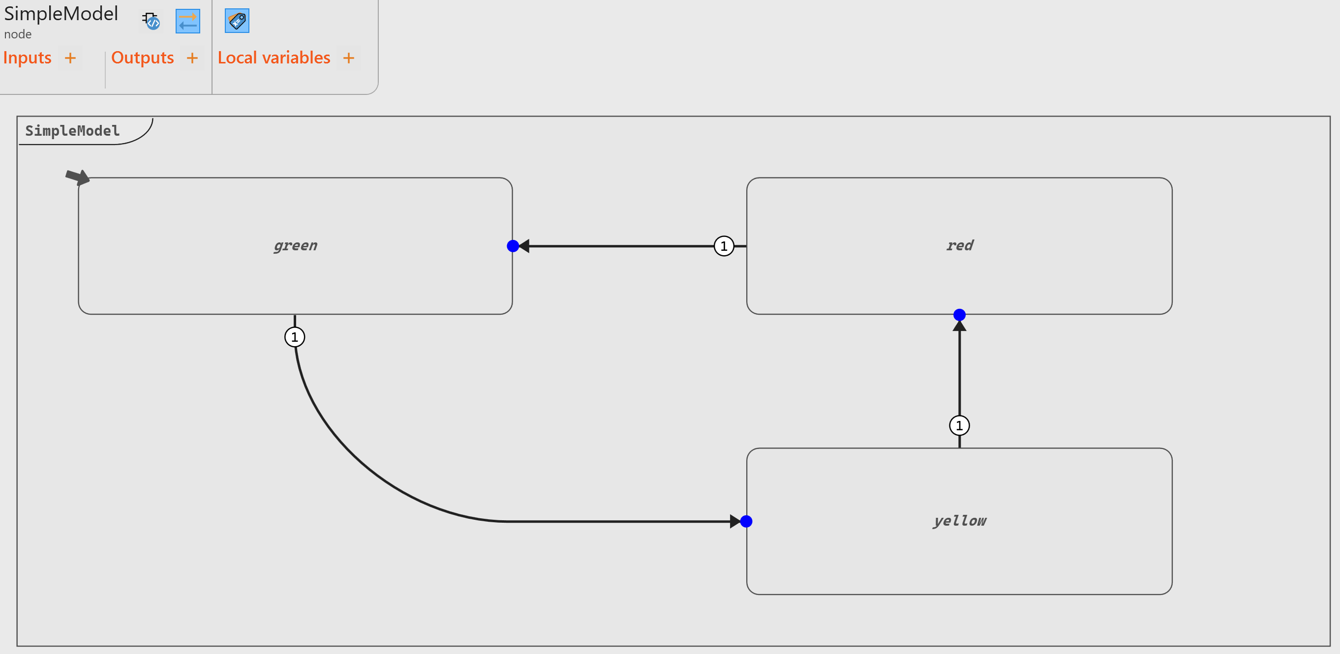
- Green (initial state, marked by the little arrow symbol)
- Yellow
- Red
- Back to step 1 and so on
An improvement to this model involves storing the current light color in the
operator’s output. To achieve this, we use an enumerate Color and
define the corresponding value to be the output light in each
state.
type Color = enum { Red, Yellow, Green, Off, BlinkingRed }node SimpleModelWithEnum ()
returns (light : Color;)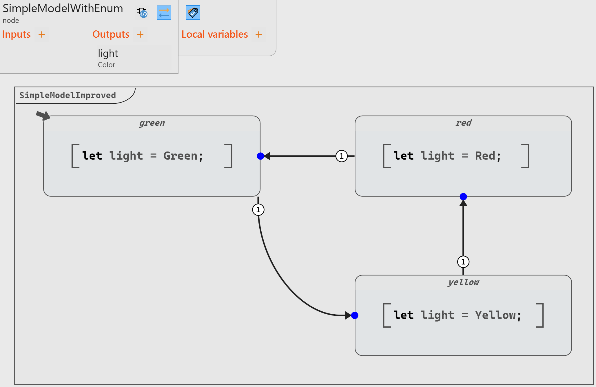
- dedicated local variable(s),
- any model that could be implemented in the main scope of the operator, including block diagrams or even other state machines.
Crossroad System with Timer for Triggering Transitions
For an accurate model, we need to add two important features:
- A timer to control the time between the different states.
- An additional state to represent a Traffic Light System at a crossroad (rather than just a single light).
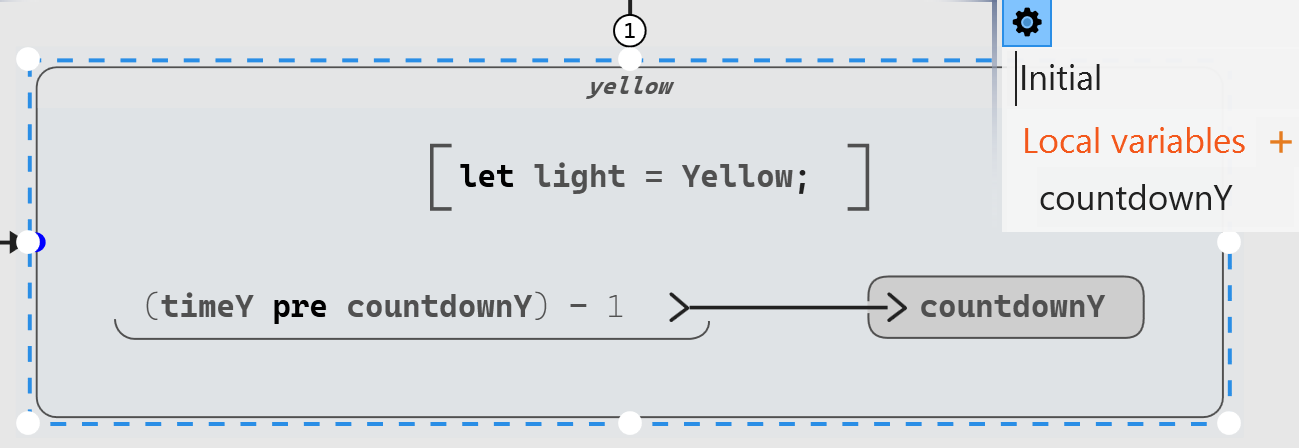
(<startValue> pre countdown) - 1Once countdown reaches 0, we can transition to a new state and start again. This is done by setting the guard value (that is, the condition) to countdown = 0.
node SimpleModelWithTimer (timeY: int32 default = 5;
                           timeG: int32 default = 20;
                           timeR: int32 default = 10;)
  returns (light : Color;)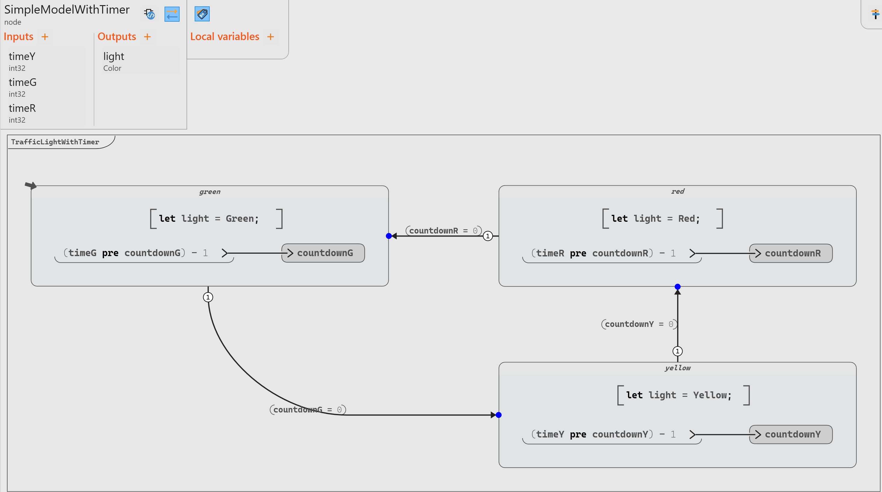
Times provided by the Scade One library Flows: it returns a given
Boolean value after a specific number of
cycles.node #pragma cg expand #end Times (count: 't ; in: bool) returns (out: bool) where 't signedThe model can be updated by replacing the computation of the condition purely on the transition and making it much simpler:
Crossroad System with Four Directions
| Phase | North-South (NS) | East-West (EW) |
|---|---|---|
| 1 | Green | Red |
| 2 | Yellow | Red |
| 3 | Red | Green |
| 4 | Red | Yellow |
The adjusted model has 3 inputs (2 for green and 1 for yellow), two outputs (the color of each light), and 4 states:
node CrossroadModelWithTimer (yellowTimer: int32 default = 5;
                              greenTimerNS: int32 default = 20;
                              greenTimerEW: int32 default = 10;)
  returns (lightNS : Color;
           lightWE : Color;)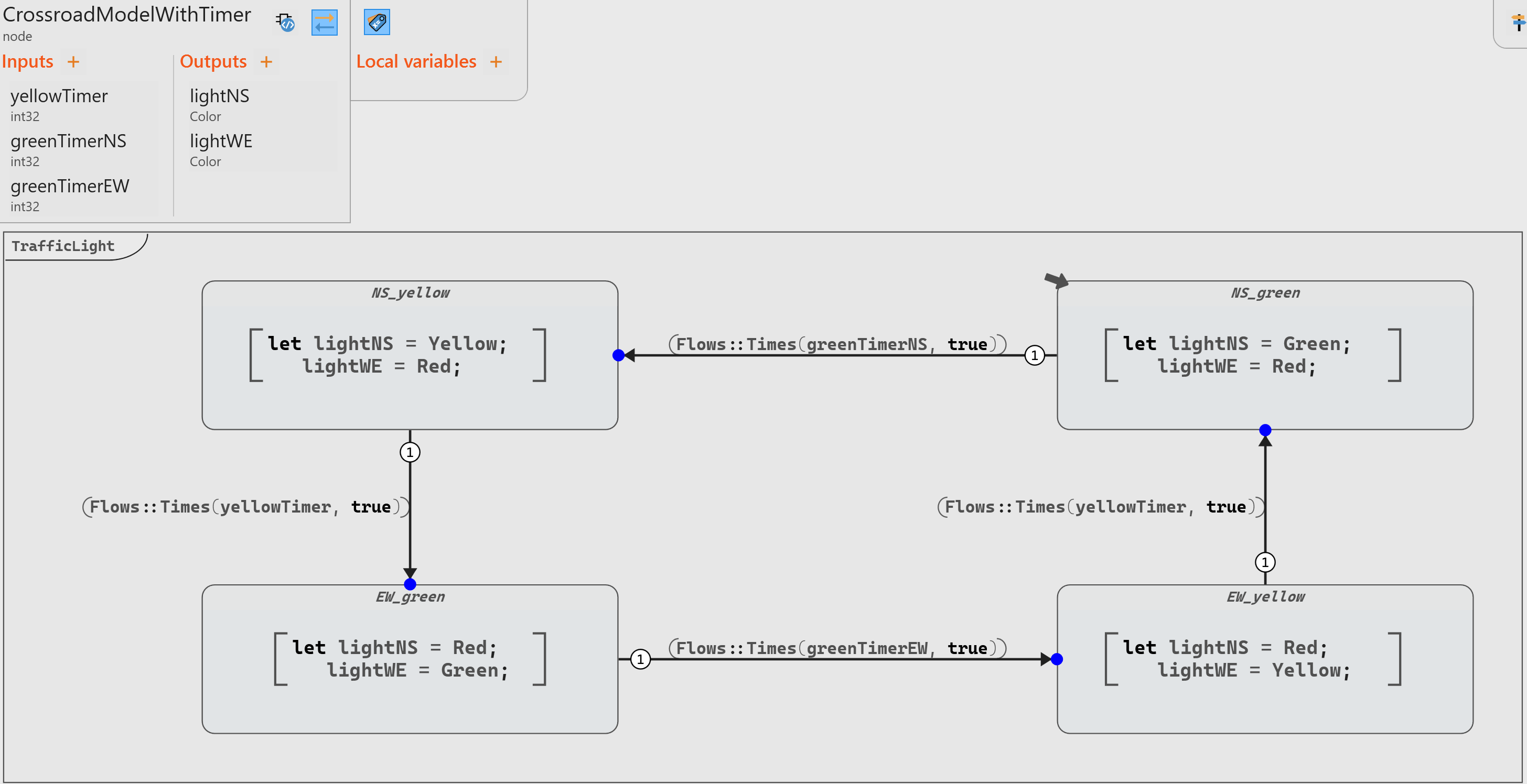
Adding an Error State
Beyond the standard trio of colors (red, yellow, and green), a traffic light may incorporate a blinking red signal to convey distinct messages. This dynamic feature is essential in various scenarios such as malfunctions, maintenance routines, intersection faults etc.
We need therefore to modify our enumerate for color to add a blinking red and a “Off” (that is, no light):
type color = enum { Red, Yellow, Green, Off, BlinkingRed };
To add an error state in our model, we need to add a transition from each state to the error state, with a priority higher than standard transitions to be sure to override any possible transition.
In addition, we can add a true initial state with all lights red when we reset our system from this error state.
Our operator becomes as follows:
node CrossroadModelWithErrorModeV1 (yellowTimer: int32 default = 5;
                                    greenTimerNS: int32 default = 20;
                                    greenTimerEW: int32 default = 10;
                                    systemError : bool default=false;
                                    systemReset : bool default=false;)
  returns (lightNS : Color;
           lightWE : Color;)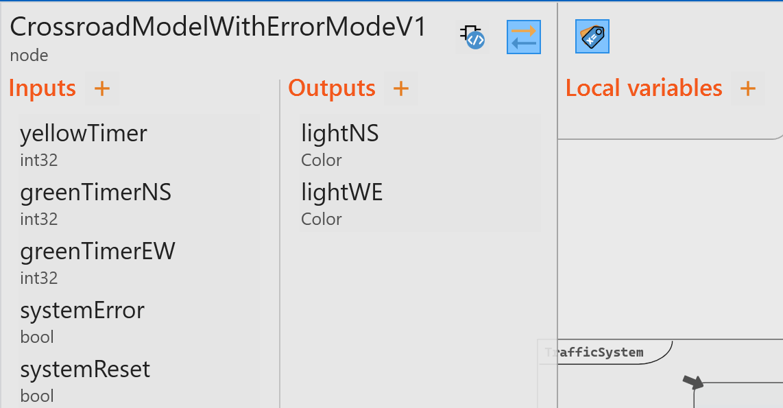
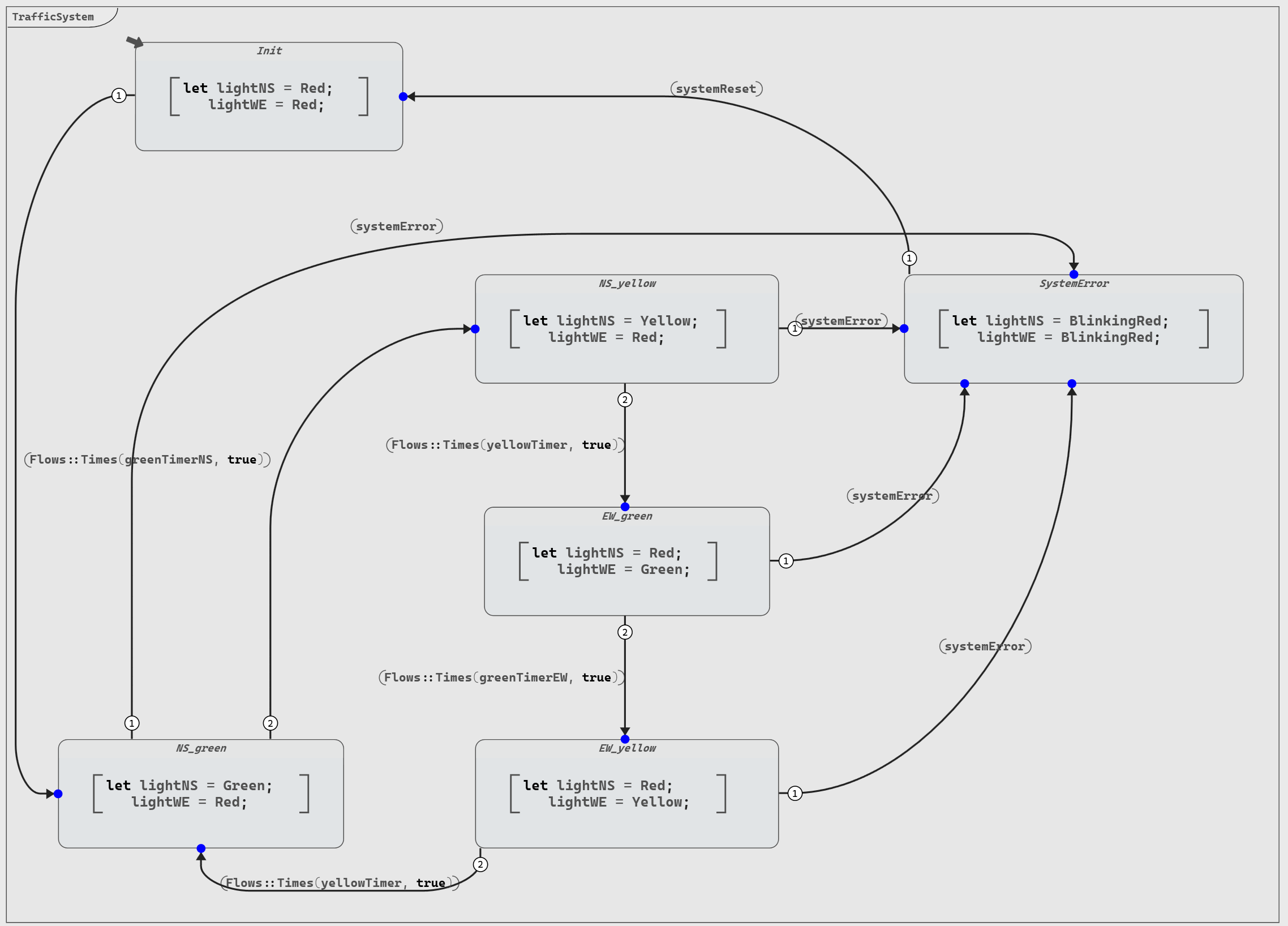
When introducing an error state in our design, several drawbacks become apparent:
- The total number of transitions is doubled due to the addition of error-handling transitions.
- We must manually prioritize the standard transitions by decreasing their priority levels to ensure that error transitions take precedence when necessary.
- The diagram readability suffers, making it more challenging to discern the system's underlying logic.
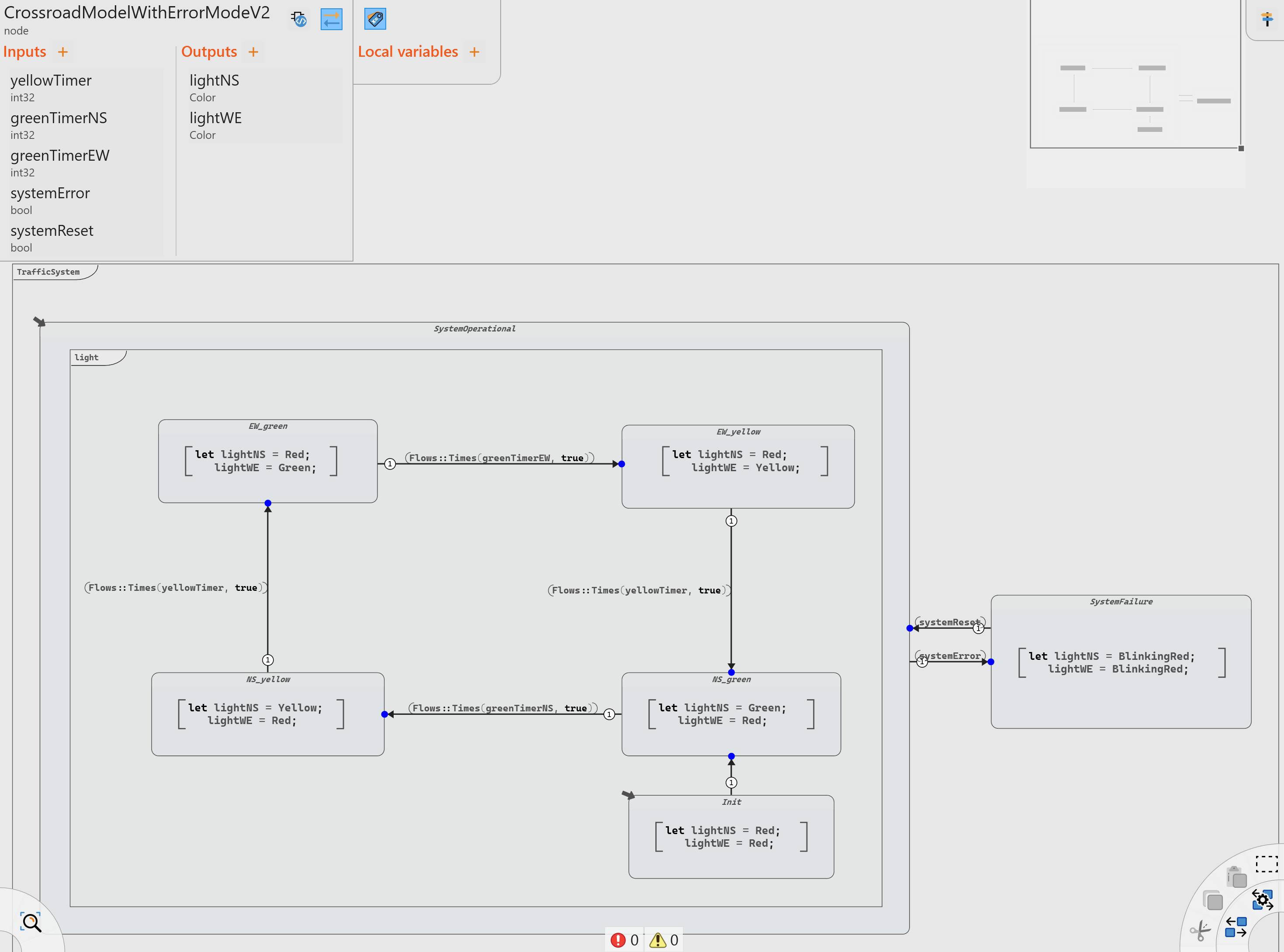
Instead of adding an error state directly, we can utilize a more effective design approach called Hierarchical Automatons. In this scenario, we create an outer automaton with two states: "SystemOperational" and "SystemError". Inside the operational state, we implement the four traffic signal states (and their corresponding transitions) and an initial state (when the system is reset).
By embracing hierarchical automatons, we create a more efficient, more organized, more maintainable, and easier-to-understand design for handling errors in our traffic signal system.
The previous model improved with hierarchical automatons is then as follows:
Debugging
One great advantage of using automatons is the ability to have a clear visualization to easily identify problems in the model.
In particular, the debugging feature of Scade One enhances the visualization and allows to:
- Trace the sequence of states and easily identify where the system deviates from the expected flow
- Isolate errors to a specific state or transition
- Provide a dynamic visualization of the execution
To improve the visualization of the model and add an interaction with the model during debug, we can use a graphical panel created with Ansys SCADE Rapid Prototyper using the Scade One Co-simulation generator configuration.
We can use this graphical panel as a Scade One operator:
node #pragma harness data_source="../resources/TrafficLightSystem.spanel" #end TrafficLightSystem(
  switchLightNS: int32;
  switchLightEW: int32
) returns (
  emitSystemError: bool;
  emitSystemReset: bool
);
To use this operator, we need to convert the enumerate representing the traffic color (including “flashing red”) to a flow of integers that trigger the change of colors. One way to do this is the following implementation (using a succession of “red” and “no color” to model the flashing red):
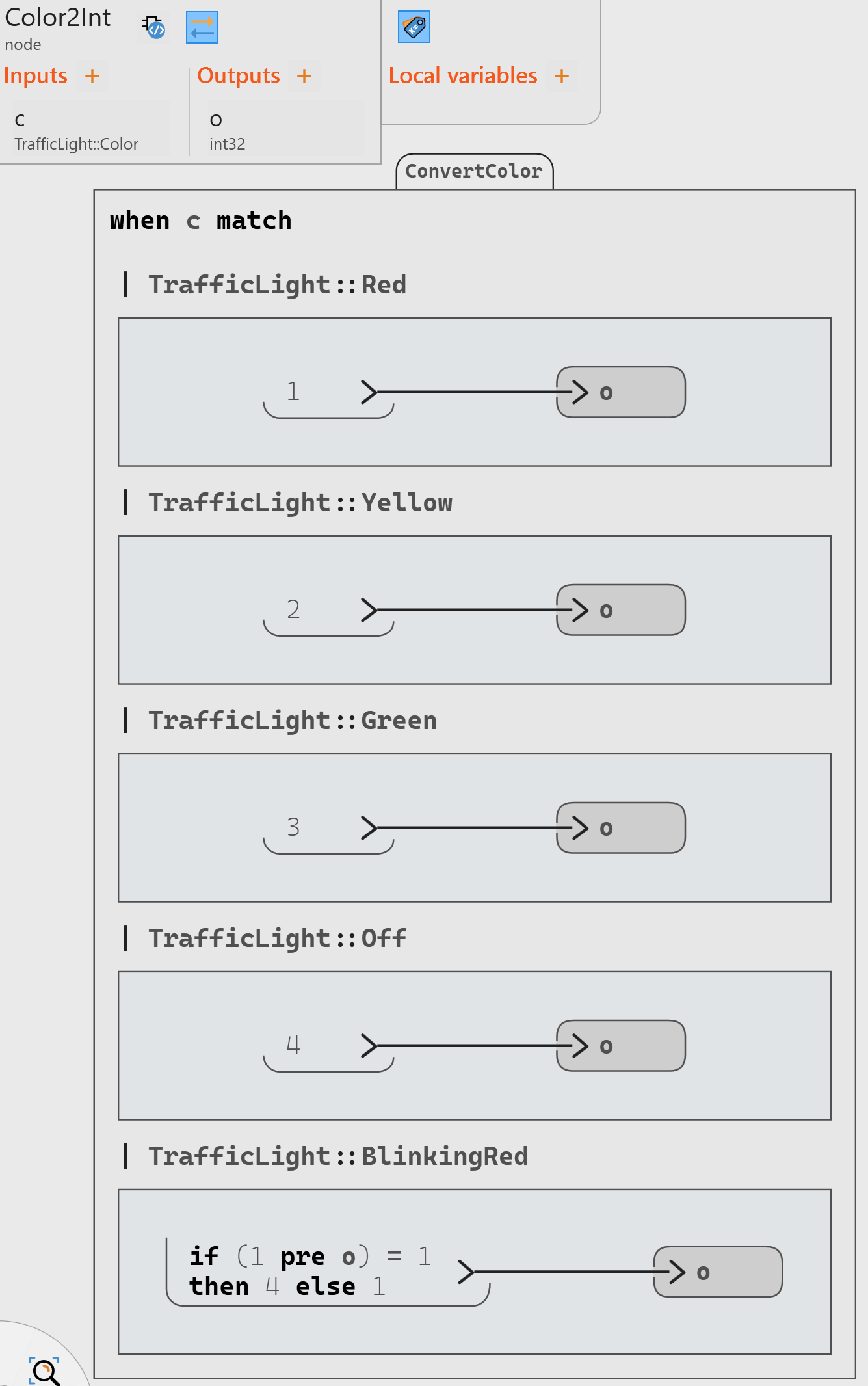
Moreover, the outputs of the graphical panel (system failure and system reset) can only be used at the next cycle, and therefore we need to use the pre operator before using them as inputs of the Traffic Light System.
The resulting debug test harness looks like this:
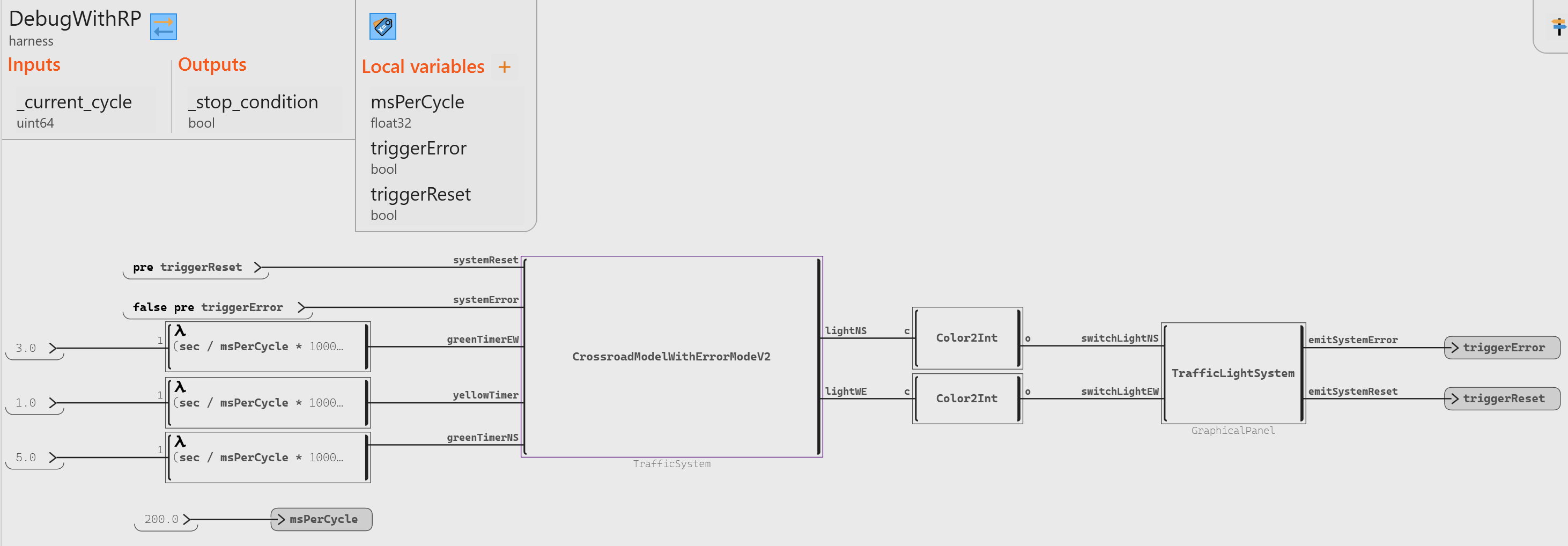
Once the debug is run, the graphical panel appears along the debug.