


How to use the ModelCenter Plug-In for Creo
This example uses the tool.prt file, which is available in the ModelCenter Plug-Ins Example Files folder in the CATIA_PlugIns folder.
- In ModelCenter, create a new Model using the File > New menu item or by clicking the New Model button on the Standard or File toolbar. Either action will open a Windows dialog to save the new workflow.
Drag the Creo component from the Server Browser and drop it into the Analysis View.

The Initialize PACZ dialog opens. Select the option that best describes the files for your workflow, then select the folder or file as needed.
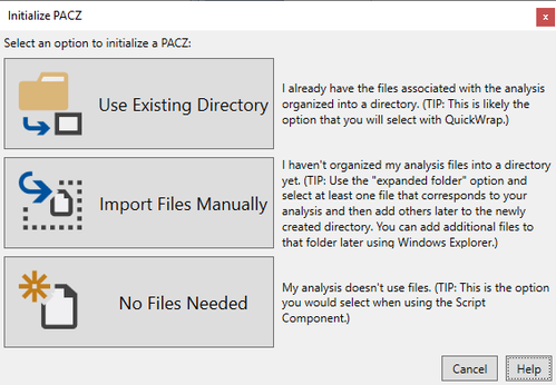
For more information on the Initialize PACZ dialog options, click the Help button in the dialog.
A CAD file selection dialog displays. Select the tool.prt file and click the Open button.
 Tip: The error below is sometimes seen when the Creo Plug-In cannot load a .prt file:
Open the .prt file in Creo and choose Save As > Save A Copy to save a .prt.1 version of the file. Remove the ".1" from the filename. Load the new copy in the Creo Plug-In.
Once the file is loaded, the plug-in will search all design parameters in the current file and extract them into the variable import dialog.
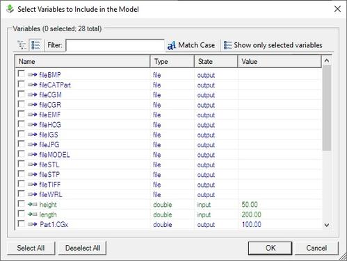
- Specify the desired design variables and click the OK button. The selected variables will be automatically shown in the plug-in.
Click the Apply toolbar button to update ModelCenter, and then close the Plug-In by closing the window.

Using the Component Tree, verify that the component is working correctly by entering the input values below and then validating the output values.
- CUTTER_DIAM = 1.5
- LENGTH = 5
- d3 = 2
- d6 = 0.8

Output Values:
- mass: 31.5337
- volume: 6.30675
- surfaceArea: 22.698
- CGx: 0
- GCy: -1.89851
- GCz: 0