


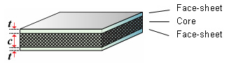
Sandwich Panel model parameters
The Sandwich Panel model predicts the performance of lightweight sandwich structures, consisting of a core material bonded to two face-sheets. These structures are used in weight-critical applications, such as transportation vehicles.
When a monolithic material is loaded in bending, the top surface is subjected to tensile loads and the bottom surface to compressive loads. These loads, which are at a maximum at the outer surfaces, reduce to zero at the neutral axis. In contrast, the shear loads, which are zero at the outer surfaces, reach a maximum at the neutral axis.
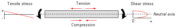
As the level of shear loading is typically an order of magnitude lower than the tensile/compressive loads at the outer surfaces, the performance of a monolithic material in bending is generally dictated by its tensile and compressive properties. This typically results in an inefficient use of material as only the outer surfaces of the component are exposed to the design load. Sandwich panel structures overcome this inefficiency by utilizing the stress distribution, and use lightweight, low performance materials in the core, and stiff, strong materials for the face-sheets. This enables the mass of the component to be minimized with little, or no, loss in performance.
| Section | Parameter | Description |
|---|---|---|
| Source Records | Face-sheet | Specify the Material record. |
| Core | Specify the Material record. | |
| Model Variables | Face-sheet thickness | You can enter a single value, list, or range. When a range is specified, the number of thicknesses must also be specified. |
| Core thickness | You can enter a single value, list, or range. When a range is specified, the number of thicknesses must also be specified. | |
| Model Parameters | Support and load conditions | These influence the stress distribution within the face-sheets and core material and determine the loading constants (B1, B2, B3 and B4).See table below. |
| Span | Unsupported length. | |
| Record Naming | Face-sheet | The abbreviated name. For example, if your source record is Aluminum, type Al. This is used to create the record names for the new materials. |
| Core | The abbreviated name. For example, if your source record is Aluminum, type Al. This is used to create the record names for the new materials. |
| Support and load conditions | Loading constants | ||||
|---|---|---|---|---|---|
| Diagram | Description | B1 | B2 | B3 | B4 |
 |
Built-in ends, central load | 192 | 4 | 8 | 2 |
 |
Built-in ends, uniformly distributed load | 384 | 8 | 12 | 2 |
 |
Cantilever, central load | 3 | 1 | 1 | 1 |
 |
Cantilever, uniformly distributed load | 8 | 2 | 2 | 1 |
 |
Simply supported, central load | 48 | 4 | 4 | 2 |
 |
Simply supported, uniformly distributed load | 384/5 | 8 | 8 | 2 |
