


Exercise 3: Calculate Limit values using the Engineering Solver
Use the Engineering Solver to convert engineering requirements into material properties, and then use these properties to filter materials in a Limit Stage.
Design requirements are often specified in terms of geometry, loading, and maximum deflections. The Engineering Solver tool converts these engineering requirements into material properties, which can then be applied in Limit Stage to screen for suitable materials.
-
Open the Engineering Solver.
Click
 Solver on the main toolbar.
 -
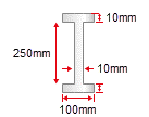
Set up the geometry for an I-beam with the following cross-section
dimensions:
Use the Cross-section list to select I-section. Enter the following dimensions and use the lists at the end of each line to select the correct units:
- Breadth, b
- 100 mm
- Depth, d
- 250 mm
- Thickness, t
- 10 mm
- Web thickness, tw
- 10 mm
- Length, l
- 5 m
As you can see, a large number of results are returned. Further selection stages can be applied to narrow down the list of potential materials (for example, setting a maximum Price).