


Using Engineering Solver
Convert engineering requirements into material properties. Then use the resulting values in a limit stage to select appropriate materials.
You can model the
following engineering loading geometries:
- Tie in Tension
- Beam in Bending
- Panel in Bending
- Shaft in Torsion
- Column in Compression
- Helical Spring
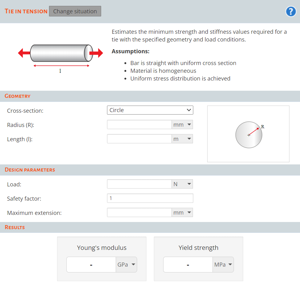
To start the Engineering Solver:
-
Click
 Solver, and select the situation that you want to
calculate engineering requirements for.
Solver, and select the situation that you want to
calculate engineering requirements for.
Use these values in a selection stage (for example, a limit stage) to filter the materials.
For further information on simulating engineering situations, see "Roark's Formulas for Stress and Strain", Warren C. Young & Richard G. Budynas.