Computing CPA RLGC Simulations
CPA setup comprises three parts: Die, Channel Components, and the VRM. You can compute an RLGC simulation for the CPA Channel Setup, or for individual sources and sinks.
To compute an RLGC simulation in SIwave:
- Click Simulation.
- From the CPA area, click Compute RLGC to open the Launch CPA window.
- Enter a name for the simulation or leave the default.
- Select either CPA Channel Setup or Individual Source/Sink Setup.
- Click Source/Sink Assignment to compute for individual sources and sinks, and set the options:
- Select one or more rows, select Source, Sink, or Float, and click Apply.
- Click OK to verify the settings and return to the Launch CPA window.
- Select the Extraction Type:
- ESD R Model – select for Pure DC resistance extraction with the Spice netlist customized for Chip ESD applications.
- RLCG Model – select to use the FEM solver. This has a high capacity and fast turn-around time, and is recommended for large PDN structures and/or having several hundreds of source terminals.
- Q3D Solver – select to use the Q3D MoM solver with adaptive meshing. This is recommended for high accuracy applications, and is ideal for lead frames and small scale packages.
- Hotspot Die Pin Group Generation – Rather than extracting every pin (which can make the netlist prohibitively large) or using a grid (which can omit hot spots), this option identifies hotspots and generates pin groups according to the specified partial R percentage, preferred grid size, and maximum number of groups appropriate. This option is only compatible with CPA Channel Setup. If you select Individual Source/Sink Setup, this option will be unavailable. Selecting this option removes the Simulation Name field, as it is not appropriate for pin generation.
Note:
Pin groups created using this method have names beginning with SmartG. See: Grouping Pins.
- Click Other Solver Settings to launch the SIwave Options window with the CPA tab selected.
- If you selected individual sources and sinks, click Launch to run the simulation. The messages window updates and the simulation completes.
- If you selected CPA Channel Setup, click Next to open the SIwave-CPA Simulation window.
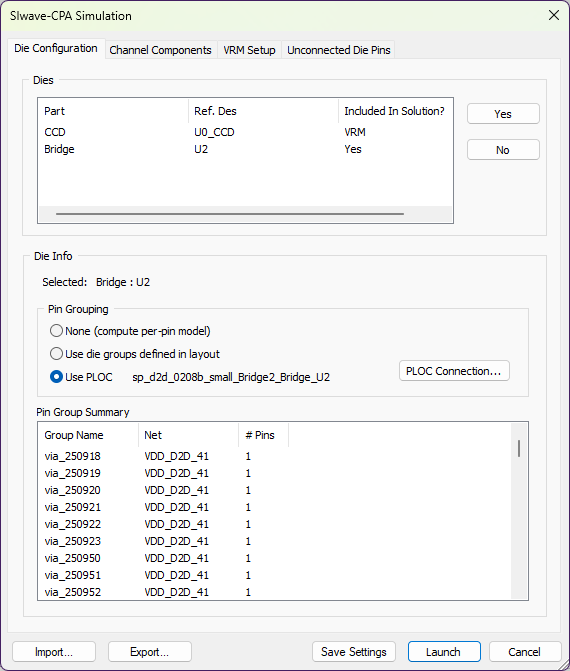
- Navigate through the tabs to set options. The Dies area lists available dies and whether they are included in the solution or are used as VRMs.
-
The available dies can be set up independently to compute per-pin model, as die groups defined in layout, or use PLOC. Dies showing Yes in the Included in Solution field are extracted. From the Die Configuration tab:
- Select dies from the list and use the Yes and No buttons to select whether they are included in the simulation.
- Select a die from the list to populate the Die Info area.
- Specify Pin Grouping for each selected die.
- None – computes per-pin model.
- Use die groups defined in layout – selects and extract only the die pins that belong to a group. To extract all pins, use a sufficiently dense grid. Create a pin group for each of the die pins.
- Use PLOC – imports and automatically connects to the die component using the PLOC Connection button. Selecting this option enables the options on the Unconnected Die Pins tab.
- Review the Pin Group Summary.
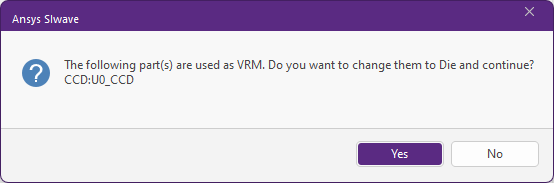
- To use a VRM-assigned part as a die, select it and click Yes to open a confirmation window.
-
Click Yes again.
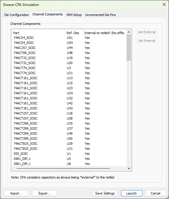
- From the Channel Components tab, review the Channel components. These
are passive components mounted on the package (other than the Die and
BGA). If any passive component has a capacitor models specified, those component pins are automatically extracted and exposed in the
Spice netlist. This helps in studying subsequent what-if scenarios without
having to go through the extraction again. If a component contains simple
R and L elements, these components are absorbed into the extraction
and not exposed at the Spice netlist level.
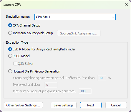
If you select Individual Source/Sink Setup, the Next button becomes a Launch button.
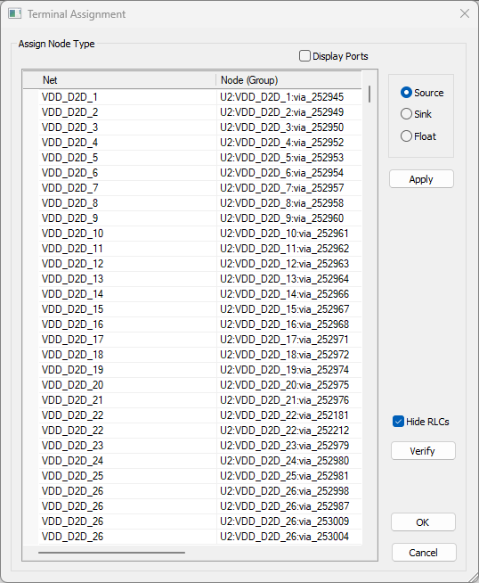
Each net is automatically assigned a Node type. Dummy and unused nets (named NC, DNU, Dummy, etc.) are set to Float by default.
To change the settings:
If a net has only sources or only sinks, the Source/Sink Count error window appears. You must correct the listed errors before proceeding.
For Hotspot Die Pin Group options, see: Grouping Pins.
- From the VRM Setup tab, review the list of available VRMs and whether they are included in the solution or are used as dies. Specify BGA components and pins that supply voltage and ground to the die. The net with the largest number of BGA component pins is designated as the Reference (Ground) net. Other nets are routed to BGA component, and
are terminated with a DC supply voltage of 1.5V by default. This value can be edited independently for each net, and the voltage level can be modified even after the extraction. If a suitable PCB model is available, it can replace the VRM model after the extraction is done. The pin groups defined on the BGA component are extracted and VRM supply voltages are distributed to these groups. If no pin groups are defined, all the pins for each net are grouped automatically, and the supply voltages are connected on net-by-net basis.
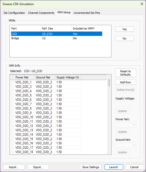
- Select VRMs from the list and use the Yes and No buttons to select whether they are included in the simulation.
- Selecting a VRM from the list populates the VRM Info area.
- Use the Add Rows and Delete Rows buttons to add and remove parts, as appropriate.
- To select parts, click the gray area adjacent to a row. You can select multiple rows using Ctrl+click or Shift+click.
- Change the Supply Voltage, Power Net, or Ground Net for each part, either by entering data in the table cells or the adjacent fields/drop-down menus. Only parts designated as VRMs can be active at one time (i.e., if a power net is defined as both a ground net and a power net, or if multiple identical power nets are created, an error message appears when users attempt to save changes).
- Press Save Settings to save changes. You can also Reset to Defaults, which will open a confirmation window. Click Yes to restore default (i.e., original) assignments. Note:
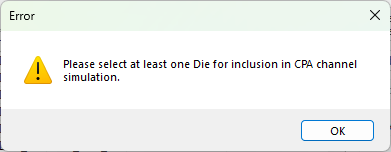
Clicking Save Settings while no dies are selected and an error window appears.
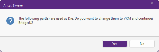
- To use a die-assigned part as a VRM, select it and click Yes to open a confirmation window.
-
Click Yes again.
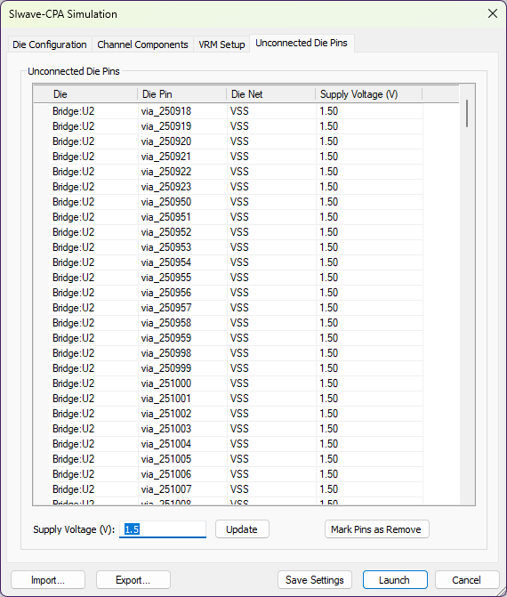
- From the Unconnected Die Pins tab, specify Supply Voltage values for any unconnected PLOC nets.
To update a voltage value, select a net, enter a value in the Supply Voltage field, and click Update. Note:
The controls on the Unconnected Die Pins tab are only available if Use PLOC has been selected for a die on the Die Configuration tab.
- From any tab, use the Export button to save the settings as an XML file. Use the Import button to load settings from an existing XML file.
- Click OK to start the CPA model extraction.
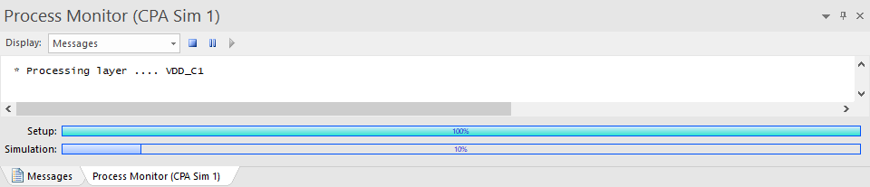
The Messages window updates with a Process Monitor tab that displays the progress.
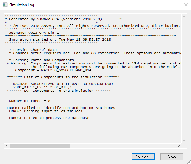
If any errors are encountered, the Simulation Log appears, summarizing them.