
3D Modeler Options: CAD Link Options
Under 3D Modeler options, the CAD Link options determine how Ansys Electronics Desktop imports designs from other CAD programs. In addition to Ansys Discovery, Ansys Electronics Desktop can import models from NX, Solid Edge, Creo Parametric, Creo Elements/Direct, AutoCAD, and Inventor projects.
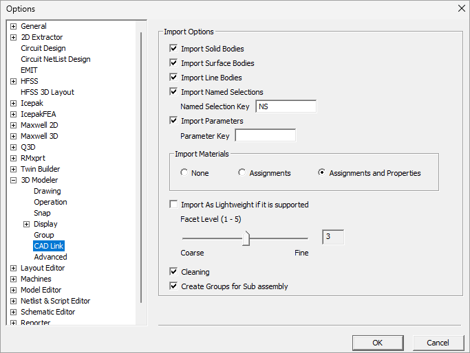
To specify CAD link settings, select or clear the following check boxes in the Import Options section:
- Import Solid Bodies – Enabled by default.
- Import Surface Bodies – Enabled by default.
- Import Line Bodies – Enabled by default. This option is not supported for Inventor models.
- Import Named Selections – Import groups of entities. The Named Selection Key can be used to filter out named selections.
- For AutoCAD: Named selections are limited to entities that are assigned to different layers.
- For Creo Elements\Direct: Named selections are limited to bodies with assigned colors.
- For Inventor: Body names cannot be assigned, so ID preserving with named selection feature is not supported.
- Import Parameters – Enabled by default. Parameters are imported as unitless values and must have unique names. Note that Discovery model parameters are imported with units. This option is not supported for Creo Elements/Direct and AutoCAD.
- Parameter Key – A string used to filter out parameters. By default, no string is entered and all parameters are imported.
- Import Material Assignments – None by default. This option is not supported for Creo Elements/Direct or AutoCAD.
- Assignments – Imports the material names without the material properties. The material properties will be obtained from a material with the same name that exists in the user's project. With this option, the system will first search for the material within the project's materials. If no matching material is found, the search will extend to the sys libraries. (See Working with Material Libraries for details on libraries.) If a material with the same name exists in a sys library, it will be imported into the project from the library. If a material with the same name cannot be found in the project, a violation will be issued after the link is created.
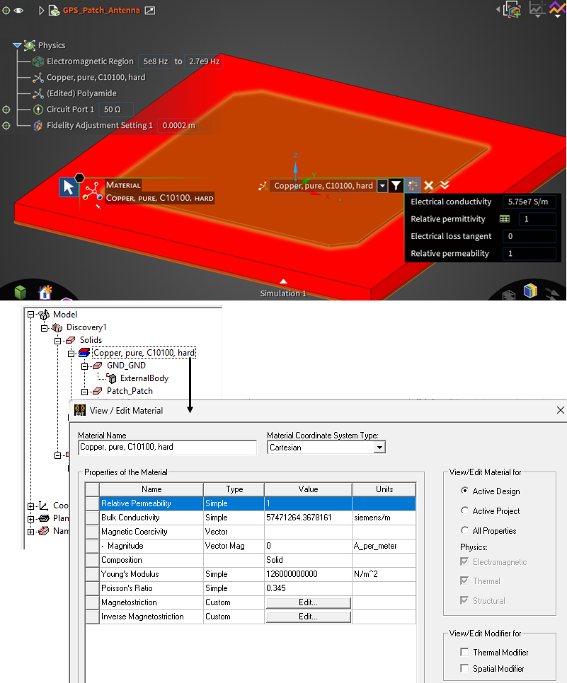
- Assignments and properties – Imports material with its material properties. The values must be in SI units. Discovery supports importing mechanical, electrical, and thermal properties. For other CAD programs, mechanical material property import is only available when connecting to Icepak and IcepakFEA designs.
A project material will be created in AEDT with imported properties. Note that if a project material with same name already exists, then it will be used instead of a new material being created. - Import As Lightweight if it is supported – This feature allows you to import lightweight geometry into a design that supports lightweight bodies. When the option is checked, the normal "unfaceted" parts in the CAD model are imported and faceted with the specified facet level. The Facet Level can be set on a 1-5 range, from coarse to fine. For CAD software other than Discovery, the faceted parts cannot be imported. For a faceted Discovery model, the facets will be imported directly, and the Facet Level setting will be ignored.
- Clean – Use to remove unwanted features when transferring geometry to Ansys Mechanical or Ansys Meshing. Clicking the check box will result in the removal of all unessential edges, vertices, and features; for example, small faces will be merged into larger faces.
- Create Groups for Sub assembly – If this option is checked, CAD sub-assemblies will be preserved. Each sub-assembly will be its own group in the Modeler history window.
For example, faces can be grouped and named in Discovery, and if this option is checked, the named selections will be preserved during import and listed in the 3D Modeler history tree under a Named Selections branch.
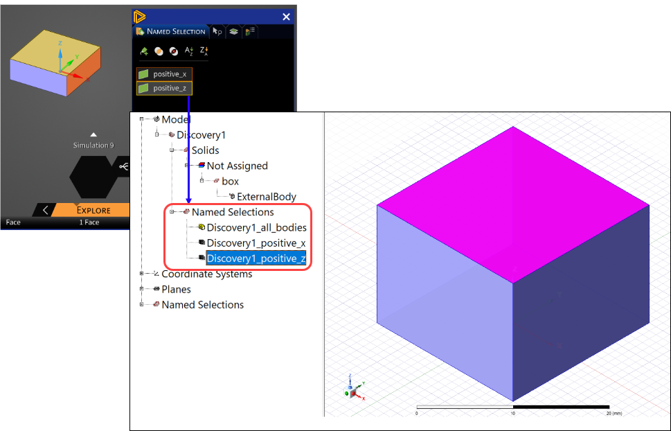
Note the following limitations for this option:
The example below shows a device imported from Discovery with the Assignments and properties option checked.
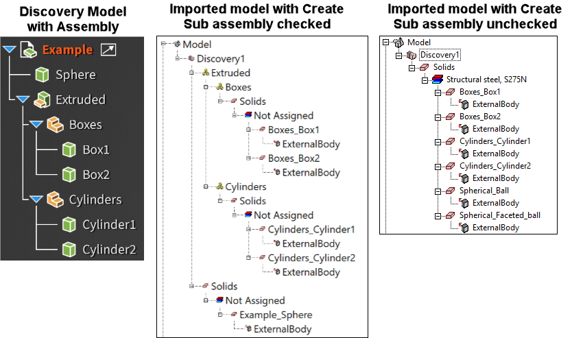
For a multi-part Discovery assembly to be preserved, its Transfer Sharing property must be set to Group from within Discovery.
Overriding CAD Link Settings for Individual Models
If you would like to override any of the settings made in the CAD Link options tab for an individual linked model, use the Properties window for the model to check, uncheck, or change a setting. An example of a Discovery model is shown below.
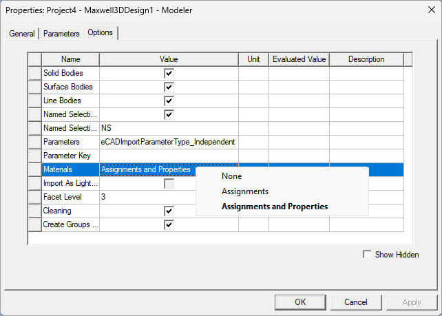
After changing parameters, refresh the link by right-clicking and selecting Generate or Send Parameters and Generate.