
Layout Component in HFSS 3D (Beta)
A Beta feature lets you import HFSS 3D Layout designs as components into HFSS 3D environment. You can have a complex layout component interact with the surrounding 3D geometries without the burden of using a 3D geometry exported from HFSS 3D Layout. This feature allows great scalability in having a complex layout geometry sit in an EMI/EMC 3D environment.
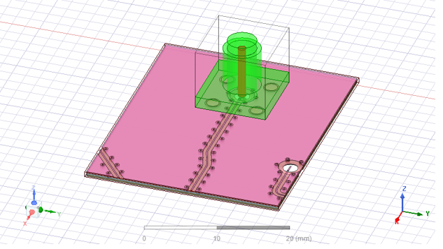
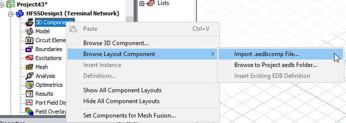
The layout component can be imported from an aedbcomp file, Project aedb folder, or EDB definition to an HFSS 3D design with terminal solution type.
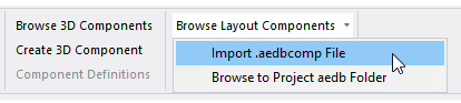
The Model tab on the ribbon also provides access to the these Layout Component commands.
Layout Component in HFSS supports relative CS placement, move, rotate, etc. Once imported, its ports will be created in the project tree The bounding box and ports have actual HFSS 3D geometry while others are not selectable and are only for visualization.
You can import a layout component into an HFSS Eigenmode design; however, be aware that excitations will not display. If you switch to another solution type, the excitations will display.
If the original layout design includes additional CS, these are included as properties to the layout component in HFSS 3D. Then as you select the original layout design to import to HFSS you choose a custom coordinate system as the reference CS. After creation in HFSS, you choose a target CS for the layout component, and the component will be moved to a place where its reference CS snaps to the target CS. This can simplify placement in HFSS.
Phi mesher is optimized for speed by generating the mesh in a layered structure. When a layout component marked as Mesh Fusion is meshed using Phi mesher, it usually has this layered structure on its four sides. The simulation currently cannot handle the case where another mesh fusion component is in contact with such a layout component on its sides.
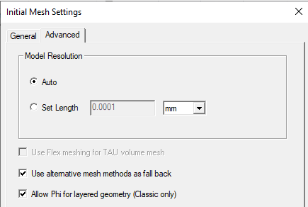
If the HFSS design has layout components meshed in native (not marked as mesh fusion), its Initial Mesh Setting dialog box is modified. The dialog box will disable the Auto and TAU mesh method and add an additional mesh method called Phi Plus.
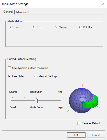
The options related to TAU on the Advanced tab are disabled.
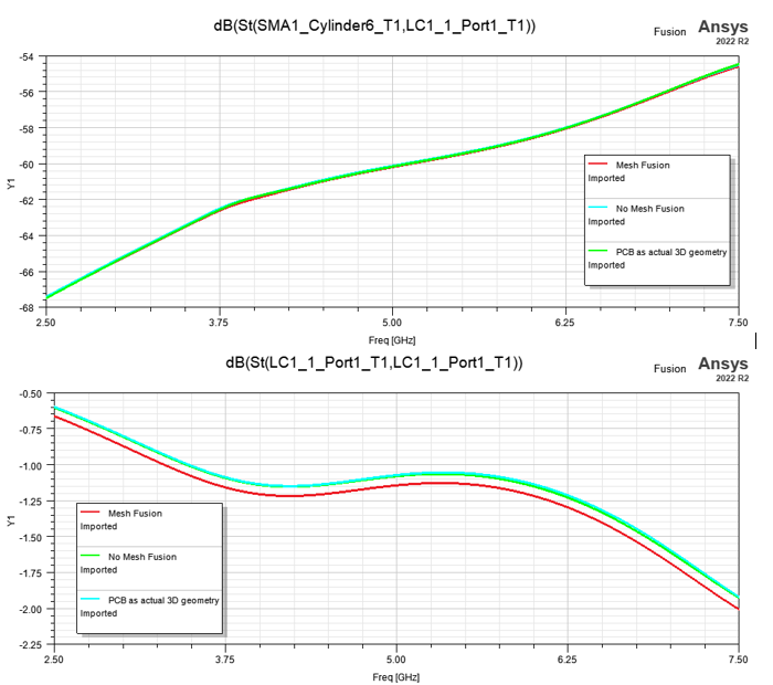
A comparison of an S-Parameter plot is shown below among 3 different cases: 1. Mesh each component using mesh fusion. 2. Mesh everything together. 3. Import the actual geometry of the layout design to HFSS directly instead of importing it as a layout component.
Supported functionalities for Layout Component in HFSS 3D include the following:
- Normal simulation workflow: Run simulation and view matrix and field overlay
- Layout geometry visualization and option to change object visualization attributes.
- Flex PCB Component support for HFSS 3D.
- Visualize RLC elements in layout components the same way as they do in 3D layout, including RLC boundaries and components that are categorized as circuit elements.
- Parametric Analysis: Using design variable to control component
- Import of custom coordinate systems from layout component design to HFSS 3D.
- Intersection Validation
- Between MCAD geometry and layout component
- Between different layout components
- Show Nets for Layout Components in HFSS 3D
- Only MCAD nets are shown now, which may connect through ECAD conductors
- Net attributes can be view through component object attributes
- Port Display
- Mesh Link
- FEBI/Hybrid Regions
- Can use non-model sheet or cut plane to plot in layout component
- Q3D DC Solve. You also choose Q3D solver to solve designs with layout components at low frequency.
- Full Mesh Fusion support
- Full interaction with other layout components, 3D components and native geometry
- Special mesh method option (classic and phi) specific to layout component.
- Enable layout components to be marked as priority if they are also marked as mesh fusion
- Record imprint steps to a script file to reproduce the same mesh in the future, similar to that in mesh fusion for 3D components
- Support parallel meshing
- Priority Component. Layout components marked as Mesh Fusion also support the priority option. The priority option provides a way to resolve component intersection conflicts with native objects. If such intersection appears, the intersecting portion will be subtracted from the native object, so that the components marked as priority stay intact and the simulation could continue.
For example, consider a design with layout component being intersected by a native box.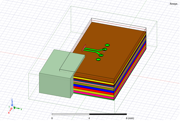
If the priority option is not marked for this layout component, the simulation reports an error. If the component is marked as priority, then the intersecting portion is subtracted from the native object, and the simulation could complete. You can plot mesh on the native objects to confirm that the subtraction is applied, and the mesh for the layout component marked as priority is intact.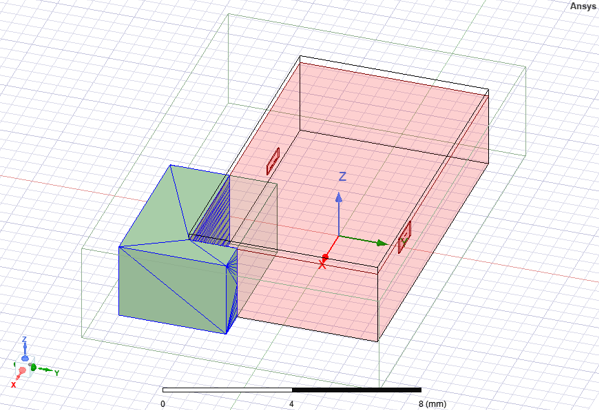
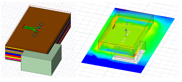
- During postprocessing, when generating field or mesh plots, anything on the interior of encrypted components will not be shown to maintain data security. The figures below show an example project with both layout components and encrypted 3D component (left) and its resultant field plot (right).
Limitations:
- Single top design EDB only
- No Derivative support
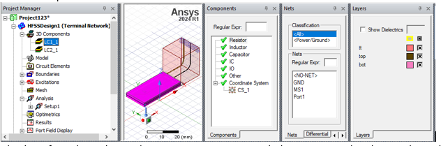
When a layout component is selected in the project tree or history tree, the Components/Nets/Layers tabs will display the information about the component in the same way as they do in a 3D layout design for that component.
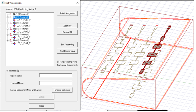
Finally, in the Net Visualization dialog box, edge ports are correctly identified as part of the nets formed by ECAD and MCAD geometries.
Encrypted Layout Component
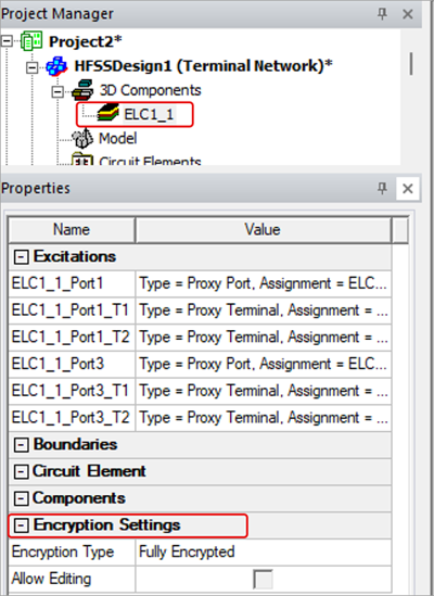
Encrypted layout components can be included in an HFSS design. If a layout component is encrypted, it will be reflected in the Properties window:
If a layout component is encrypted, note the following:
- Encrypted layout component definitions cannot be edited.
- Only exposed objects of an encrypted layout component are visualized in the modeler window.
- The snapping points will only be created for visualized objects.
- The circuit element visualization will be turned off.
- The object attributes dialog box and the Nets/Layers tab will only show net and layers containing the exposed objects.
- The footprint of ports from the encrypted layout component will not be created.
- The Net Identification dialog box will identify connections between an encrypted layout component with outside objects only through the layout component’s visible objects. The hidden objects from the encrypted layout component will only be used to identify internal connections but can potentially link to the outside objects through the layout component’s visible objects. Only the visible objects from the layout component will be displayed in the final connection information.
- All files in the aedb and aedtresults folders related to the encrypted layout component are encrypted.
- All preprocessing and meshing features for regular layout component are also supported by the encrypted layout component, such as mesh fusion, parametric analysis, and priority level.
- All generated temp files related to the encrypted layout component, with the exception of the truesurface, lrd, and seedmacro files, are encrypted.
- During postprocessing, the encrypted layout component’s nets and layers cannot be used to plot field/mesh plots.
- Field/Mesh information about encrypted layout components will be hidden during postprocessing.
Related Topics
Using Layout Component in HFSS 3D Process Flow
Visualization for Layout Components in HFSS 3D
Mesh Region Options for Layout Component
Visualization for RLC Boundaries and Component Groups Designated as Circuit Elements
Replacing or Editing Layout Components
Using Layout Custom CS for Placement in HFSS 3D
Flex PCB Components in HFSS 3D
Field Plots on Layout Component's Layer or Net
Using the Fields Calculator with Layout Component in HFSS 3D