
Inserting a 3D Component into a Design
Once you save one or more components to a library and create target coordinate systems in the design where you intend to place the component, you can do any of the following:
- Right-click the 3D Component icon in the Project Manager or use the Draw > 3D Component Library commands to browse your folders or libraries
- Use the View > Component Libraries to display a Component Libraries window to navigate installed libraries.
- Insert an instance of a component by right-clicking the 3D Component icon in the Project Manager and selecting Insert Instance.
From the Component Libraries window, you can navigate to the directory of installed components, as well as any in your Personal Library. The hierarchical tree display includes Favorites and Most Recently Used branches. 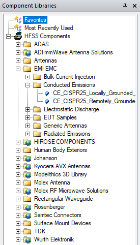
You can select any component from the library, and drag and drop to insert it in the design.
When you drag the component into the Modeler window or use the Browse function to select and place a 3D component, it appears as an outline to make it easier to place. The diamond-shaped marker designates the placement location.
Move the cursor in 3D modeler window to snap to a point where you want to insert the component and then click to place. While the component is being moved, the Measured Data window appears and reports the position in the Reference and Current coordinate systems.
The position of the 3D component will be reported in the Properties window. It can also be edited from this window.
Double-click any model in the component libraries to
Selecting Browse 3D Component lets you navigate directories via a browser window.
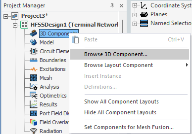
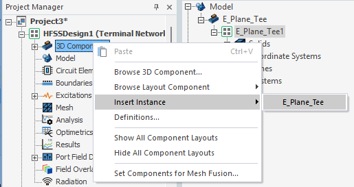
If you have previously inserted a 3D Component, the Insert Instance command is enabled on the menu. You can use this command to easily insert another instance of a 3D Model already in the design.
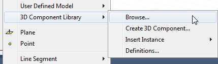
Another option to select a 3D component is to click Draw > 3D Component Library to access the Browse and Insert Instance menus.
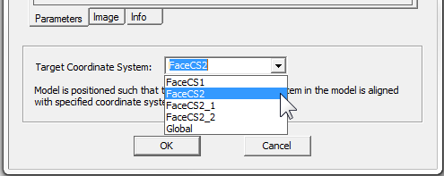
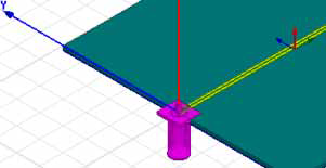
A target coordinate system provides a location for a component. For example, a design includes two additional coordinate systems:
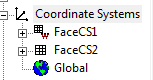
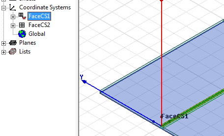
Selection of a coordinate system in the History tree displays a potential location for inserting a component.
To Insert a 3D Component from the Menus
- Right-click the 3D Components icon
in the Project tree to open shortcut
menu. You can select Browse 3D Component to
use a browser window to navigate the file system to the component.
- Use the menu to select the Target Coordinate
System if any have been defined in addition to the Global coordinate
system. The target coordinate system that you select is highlighted in
the modeler window.
- When you click OK, the outline of the component appears in the Modeler window, and you can then drag it to the desired location and click. The component is placed at
the coordinate system you selected.
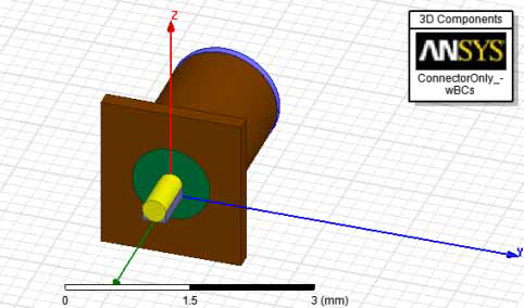
- If the component has a logo defined, the image is always displayed in the upper right of the modeler window.
- If you have used Browse, select a component and click Open. If you use the Insert Instance menu, select the component name.
Selecting a 3D component file opens a window that includes Parameters, Image, and Info tabs that display the component attributes.
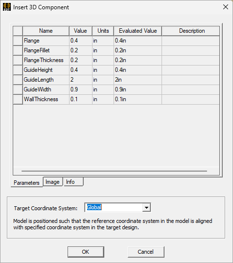
You can edit parameter values, and assign variables or expressions for parameters.
If you have previously inserted a component into a Project, the shortcut menu for the 3D Component displays that component so that you can easily insert another instance of the same component.
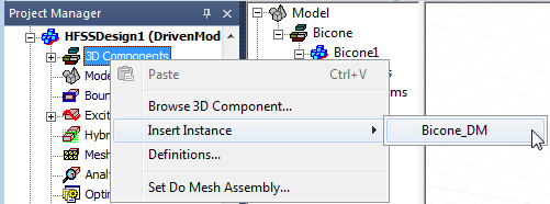
This action will open the Insert 3D Component window to the Parameters tab.
If the component has been encrypted, you may be prompted to enter a password. If you insert another instance of the same component, you do not need to enter the password again for that component.
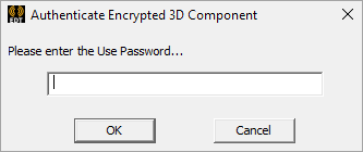
You have three tries to enter the correct password. Upon successfully entering the password, the Insert 3D Component window opens with the Encryption tab displayed.