
Editing a Layout Component Definition
All layout components in
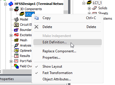
Once clicked, it opens the design containing the EDB definition of the layout component in a separate project to allow for any editing. Once a layout component is edited, either through a parent 3D layout design or through this command, all designs of different types that use this component update it accordingly.
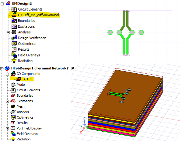
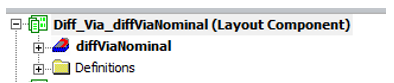
For example, in an Ansys Electronics Desktop project, multiple designs of different types can have layout components of the same definition. Below is an example project where both an HFSS 3D Layout design and an HFSS design have a layout component with the definition “Diff_Via_diffViaNominal”.
In addition to editing the source layout design using the Edit Definition command, you can edit the layout component's local settings, or replace it with a different component, using the Replace Component command.
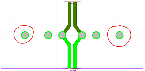
In the source design, you can edit the layout component however you want. This example adds two more vias on the left and right side as shown in the figure below.
After editing, you can save the source design, and a dialog box opens for you to confirm the changes.
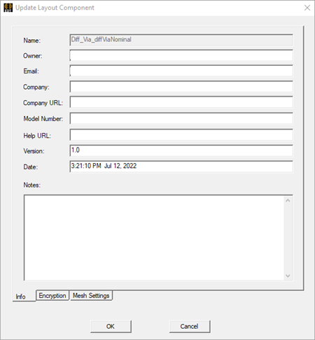
Once the changes are confirmed, both the HFSS 3D Layout design and the
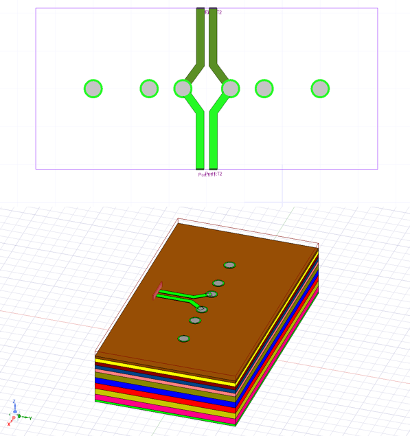
The editing is not undoable. After saving the source model, the target project is automatically saved, and the undo stack is cleared.
While editing, you may choose to encrypt the layout component to limit its use and/or limit its editing.
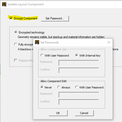
With the Ansys Electronics Desktop 26r1 release, only HFSS 3D Layout and HFSS support encrypted layout components.
If the layout component is encrypted, a dialog box with warning messages alerts you about the potential impact to the designs containing this layout component. And after editing, all encrypted layout components are deleted from any target designs that do not supported encrypted layout components. A warning message appears for each deleted layout component.