
Setting IcepakFEA Options
To set IcepakFEA options in Electronics Desktop:
- Click Tools > Options > General Options.
- In the left pane, expand and select IcepakFEA.
The Options window appears, displaying General options.
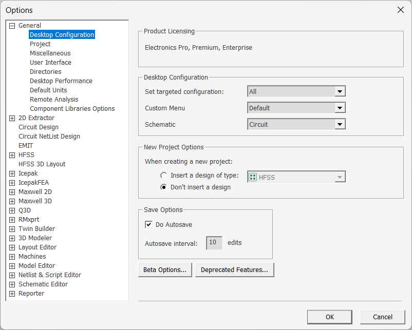
The IcepakFEA options branch expands, and the IcepakFEA General options display by default:
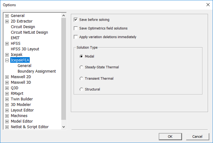
Use the tree in the left pane to select a group of options.
Under IcepakFEA General options, you can set the following:
- Save before solving – forces a full save before running the solver. If a simulation is started while another is running, you will be asked if you want to solve without saving first. You can run multiple simulations, and if you have not edited the project in between solutions, crash recovery will work. In any case, you can start a new solution while running another without having to abort the current simulation.
- Save Optimetrics field solutions – when enabled, saves the field solution data for every solved design variation.
- Apply variation deletions immediately – select to save disk space.
- Solution Type – Four solution types are available for IcepakFEA projects. Choose one of the following two options:
- Modal: Determine natural frequencies and vibration mode shapes.
- Steady-state Thermal: Perform a steady-state heat transfer analysis to determine temperature and heat flux distributions.
- Steady-state Thermal: Perform a time-dependent heat transfer analysis to determine temperature and heat flux distributions.
- Structural: Determine stresses and deformation induced as a result of thermal expansion or contraction of solid objects.
Under IcepakFEA Boundary Assignment options, you can set the following:
- Use wizards for data input when creating new boundaries: When applicable a step-by-step wizard walks you through the assignment of new boundary conditions. Existing boundaries are edited through the conventional boundary dialog box.
- Duplicate boundaries/mesh operations with geometry – when enabled, boundaries and mesh operations assigned to geometry are copied along with the geometry. That is, duplicating the geometry also duplicates the boundary and mesh operation assignments.
- Visualize boundaries on geometry – when enabled, boundaries are visualized on the model geometry when selected in the Project Manager.