
STM Network Extraction
Surrogate Thermal Network Builder creates, trains, and exports a Delphi-like Surrogate Thermal Model (STM) that is boundary condition-independent and can be used to emulate the thermal behavior of the integrated circuit (IC) package. The toolkit allows you to select specific geometric features from the Detailed Thermal Model (DTM), including external faces and heat sources. These features have two primary purposes: to inform the DTM simulations for data production and to fully define the STM’s external geometry.
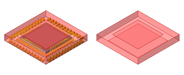
The Surrogate Thermal Network Builder process consists of creating parametric trials for steady-state and transient designs to generate designs containing an STM that feature a network based on the training data. The simplified STM design (geometry and boundary conditions) enables faster, shorter meshing and analysis times. The following image displays a QFN package as a detailed thermal model (left) and surrogate thermal model (right).
The Surrogate Thermal Network Builder workflow consists of three main steps:
- Geometry extraction: after specifying the package type under Surface Selection, click Extract Geometries to capture geometries and group them.
- Setup creation: after specifying the parametric origin and associated settings, click Add Setup to add the setup to the Active Setup(s) list. Then, right-click the setup and select Create Setup to initiate a three-step process. Icepak specifies thermal boundary conditions, assigns monitors, and creates a parametric setup. After the process is complete, all of these items appear in the Project Manager.
- Transient design creation: after running the steady-state to create the training data, click Create Transient Design to generate a transient design based on the selected steady-state design. This includes a consistent set of thermal boundary conditions and monitor assignments, and parametric setups. In addition, the solver settings are automatically updated to enable data generation for a dynamic surrogate model.
|
Surface Selection |
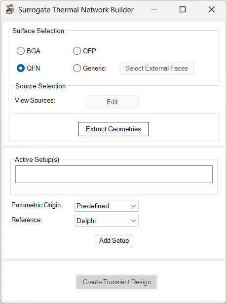
Under Surface Selection, select the package type for the network extraction. Select Generic for packages that are not BGA, QFP, or QFN created using an Icepak > Toolkits > Geometry toolkit. For generic packages, click Select External Faces to export groups of external faces manually or automatically and Select Internal Faces to manually export groups of internal faces. See External Faces Editorfor more information. |
|
|
|
|
Source Selection |
Click View Sources to open the Edit Source dialog box. Sources present in the design are displayed in the list. If needed, select a source and click Delete Selected Source to remove it from the analysis. Click Refresh Sources to update the list of sources. Click OK to close the Edit Source dialog box. |
|
|
|
|
Extract Geometries |
Click Extract Geometries to finalize the collection of external faces, internal faces, heat sources, and their related properties. When the process is complete, the Extract Geometries button appears green. |
|
|
|
|
Active Setups |
Active Setups lists the parametric setups added to the design. See Active Setup Options for more information. |
|
Parametric Origin |
For Parametric Origin, select Predefined, Import from File, or Sampling. |
|
Predefined |
For Predefined, select Delphi, Jedec, or Demo. Predefined is only available for packages with one heat source. If your package has multiple heat sources, this option is not available. |
|
Import from File |
For Import from File, click Browse to open the Select CSV file dialog box. Navigate to your working directory, select the .csv file, and click Open. |
|
Sampling |
For Sampling, enter a number of Samples and the Standard Deviation. If needed, enable Include Ambient Temperature. Also, enabled Uniform Sampling to open the Configure Uniform Sampling Ranges to specify a range of values for source power and ambient temperature (if enabled). See Configure Uniform Sampling Ranges for more information. |
|
Add Setup |
Click Add Setup to add the specified parametric setup to the design. |
|
|
|
|
Create Transient Design |
Create Transient Design is enabled after you create at least one active setup. Click Create Transient Design to generate a transient design based on the steady-state design. A transient parametric setup is created and is ready to analyze in the Project Manager. |
External Faces Editor
In the External Faces Editor, use the External Group Manager to manually create groups of external faces based on geometry selected from the 3D Modeler window or the History tree. Alternatively, you can click Automatic Extraction of Bounding Faces to automatically identify the external faces touching the package's bounding box and categorize them in groups.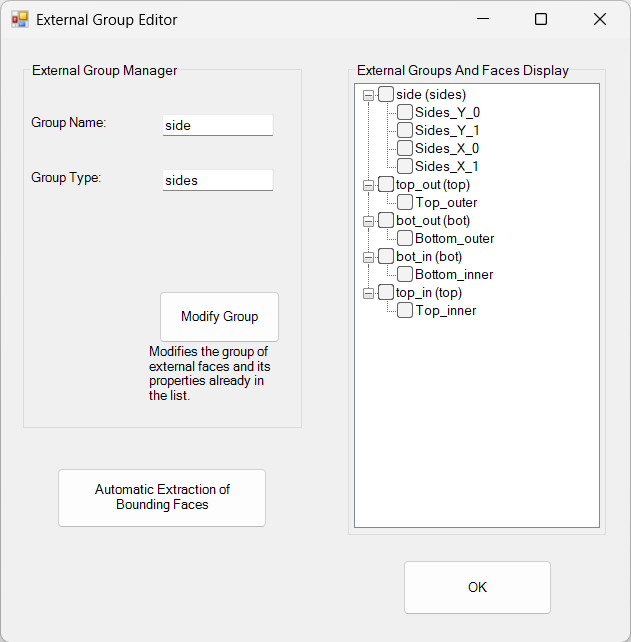
| External Group Manager | ||
|---|---|---|
| Group Name |
Enter a Group Name for the group of external face geometry. |
|
|
Group Type |
Enter a Group Type for the group of external face geometry. |
|
|
Create Group |
Click Create Group to save the group name and/or type changes. The Create Group button appears when a group is selected in the Groups tree. |
|
| External Groups and Faces Display | ||
| Group Tree | The External Groups and Faces Display tree lists the groups and associated faces you've created. If needed, select a group and modify its name or type. From a group's right-click menu, you can unite all the faces into one piece of geometry, delete the group, or delete all groups. From an external face's right-click menu, you can split the face, remove it, or move it to a different group. With multiple faces selected, you can split the faces, unite them, remove them, or move them to a different group. | |
|
Automatic Extraction of Bounding Faces |
Click Automatic Extraction of Bounding Faces to automatically identify the external faces touching the package's bounding box and categorize them in groups. After confirming the bounding box selection, the Get Boundaries dialog box appears. Choose whether to create single sheet geometry for each of the six bounding surfaces or to split the sheets into more than one based on the intersecting geometry. Splitting the geometry will require more time to generate all of the geometry. |
|
| OK | After creating all external groups, click OK to save the external groups and close the External Faces Editor dialog box. | |
Active Setup Options
In the Active Setup(s) list, right-click a setup to display the following options.
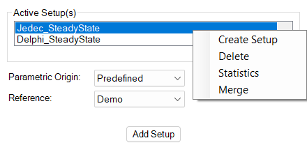
- Create Setup: Click Create Setup to generate boundary conditions, monitors, a solution setup, and parametric setup.
- Delete: Click Delete to remove the selected setup.
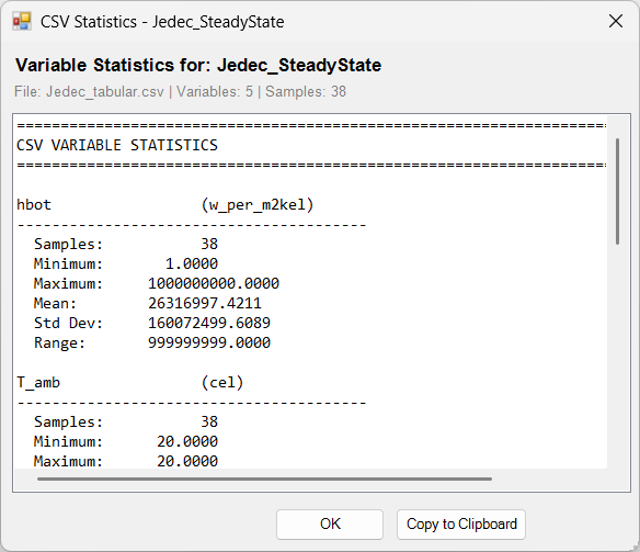
- Statistics: Click Statistics to display the project variable statistics for the selected setup.
The dialog includes data for each variable included in the setup.
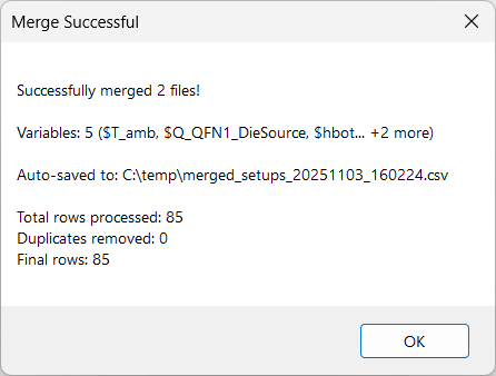
- Merge: If more than one setup is in the list, click Merge to combine the two setups into one setup.
Note:
To merge setups, the setups' variable sets must be identical, though their order can differ. Merging accounts for any duplicates across the different setups in the list.
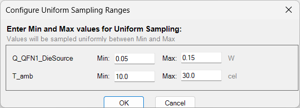
Configure Uniform Sampling Ranges
In the Configure Uniform Sampling Ranges dialog box and specify the Min and Max power and ambient temperature values (if enabled) to be sampled for the analysis. The values used are uniformly sampled between the specified minimum and maximum.
Solve the Steady-State Design for Training Data
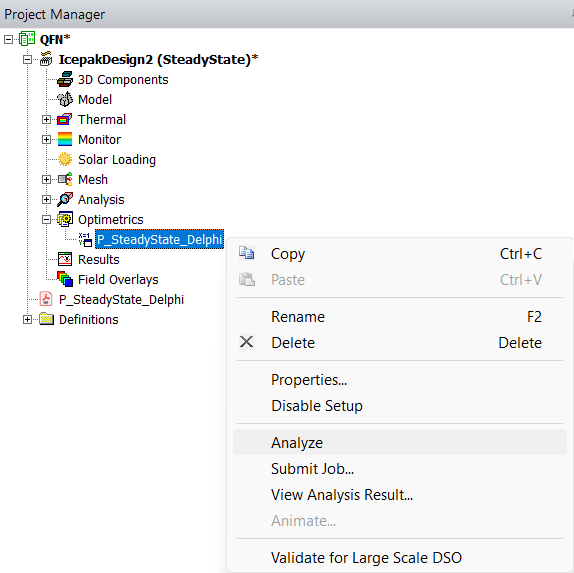
After you click Create Setup from the Active Setup(s) options, a new design is created with boundary conditions, monitors, a solution setup, and a parametric setup. To solve for training data, right-click the parametric setup in the Project Manager under Optimetrics and select Analyze.
The naming convention for the newly created analyses is as follows. For an analysis named P_Sampling_25Samples_SteadyState:
P = Parametric
Sampling = Parametric Origin selection
25Samples = Number of Samples (Sampling only)
SteadyState = Solution type
Monitor the status of the training process in the Progress Window.
Create the Steady-State Surrogate Thermal Model
After generating the training data by running the parametric trials, create the STM. In the Project Manager, right-click the design and select Export > Create STM.
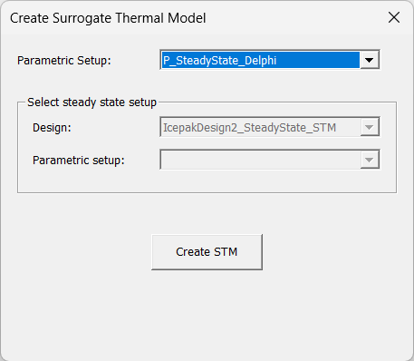
From the Parametric Setup drop-down list, select a setup. If you created more than one steady-state design for training data, under Select steady state setup, select a Design and Parametric Setup. Click Create STM to create a new design that includes a network boundary condition that represents the surrogate thermal model based on the package.
A PDF document that contains the STM analysis data is created. Double-click the PDF in the Project Manager to open it.
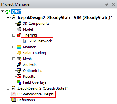
Create a Transient Design
After you create an STM based on the steady-state training data, create a transient design to create transient training data. Double-click the newly created steady-state design with the STM to make it the active project. In the Surrogate Thermal Network Builder dialog box, click Create Transient Design.
A new transient design is generated with the same boundary conditions, monitors, solution setup, and parametric trials.
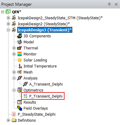
Under Optimetrics, double-click the parametric setup to open the Setup Sweep Analysis dialog box. On the General tab, enable Include next to the parametric analysis.
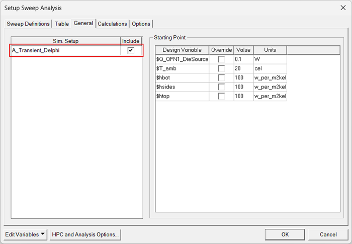
Click OK to close the dialog box.
Solve the Transient Design for Training Data
To solve for training data for the transient design, right-click the parametric setup in the Project Manager under Optimetrics and select Analyze.
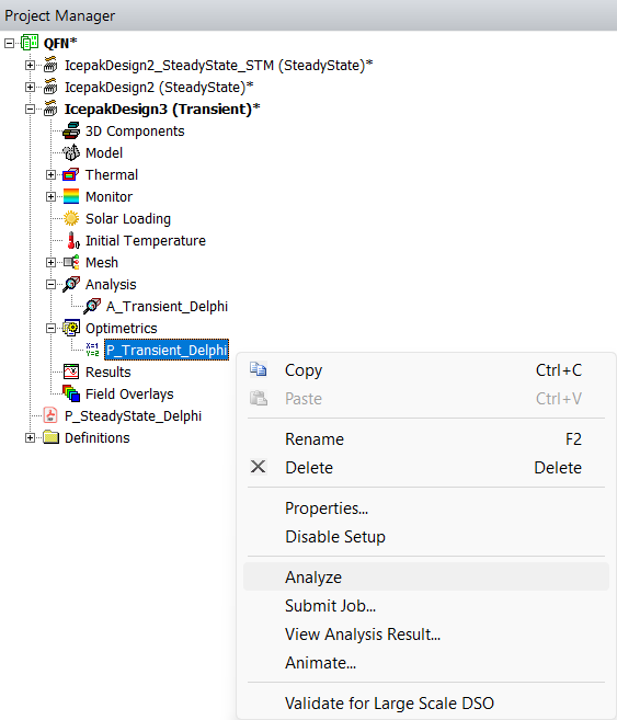
Create the Transient Surrogate Thermal Model
After generating the training data by running the parametric trials, create the STM. In the Project Manager, right-click the design and select Export > Create STM.
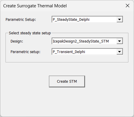
From the Parametric Setup drop-down list, select the steady-state setup (if there are multiple). Under Select steady state setup, select the steady-state STM Design and transient Parametric setup. Click Create STM to create a new design that includes a network boundary condition that represents the surrogate thermal model based on the package.
A PDF document that contains the transient STM analysis data is created. Double-click the PDF in the Project Manager to open it.