Assigning a Transient Excitation
These instructions assume the user has already set up and solve a Transient Analysis on the design with all appropriate drivers and receivers attached to ports. Transient currents flowing into each port are captured and converted to frequency-domain sources during execution of DCIR simulations. Users can also record these steps using the Record Script function on the Automation tab, then run the resulting Python script to set the specified excitation source. Refer to Using a Python Script to Configure an SIwave Solution Setup.
Follow these steps to select a Circuit or HFSS 3D Layout transient excitation source to use as an external source for simulation.
-
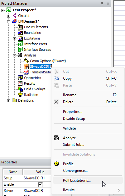
From the Project Manager window, expand the active design folder (e.g., Test_Project) > subdesign (e.g., EMDesign1) > Analysis. Then right-click the DCIR solution setup (e.g., SIwaveDCIR 1) and select Pull Excitations to open the Pull Excitation Options window.
-
From the Pull Excitation Options window, do the following:
-
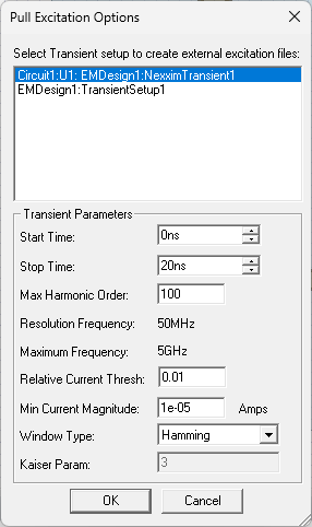
Select a Transient setup to create external excitation files (e.g., Circuit1:U1:EMDesign1:NexximTransient1).
-
Make any appropriate changes in the Transient Parameters area. By default, the data that is pushed to a dynamically linked project is automatically calculated. The start and stop times must lie within the transient simulation time limits.
- Start Time – enter the beginning time of the transient interval.
- Stop Time – enter the ending time of the transient interval.
- Max Harmonic Order – specify the maximum number of harmonics to include when calculating frequency-domain data. By default, this value is set to half of the transient simulation’s sample points, corresponding to the Nyquist frequency. Together with Start and Stop Time, this determines Resolution Bandwidth and Maximum Frequency.
- Reference Frequency – displays the frequency used as the reference point for harmonic calculations.
- Maximum Frequency – displays the highest frequency included in the data.
- Relative Current Threshold – enter the minimum relative current level to include in the excitation data. Signals below this threshold are ignored.
- Min Current Magnitude – specify the minimum current magnitude to include in the excitation data.
- Window Type – select a windowing function from the drop-down menu (e.g., Hamming, Hanning, Kaiser, Welch, etc.). Non-rectangular windows apply a processing loss (coherent gain), which is automatically compensated when excitations are pushed to linked projects.
- Kaiser Param – if Kaiser is selected from the Window Type drop-down menu, enter the beta parameter that controls the trade-off between main-lobe width and side-lobe level. Only editable if Kaiser is selected.
-
-
Click OK to close the Pull Excitation Options window. If the excitation is accepted, a confirmation message appears in the Message Manager window.

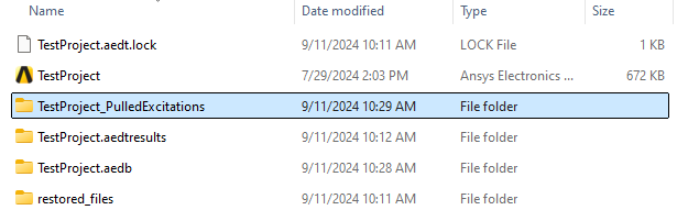
Within the same directory where the project is saved, a folder is created called <ProjectName>_PulledExcitations, which contains the newly created excitation files referred to in the Message Manager window.
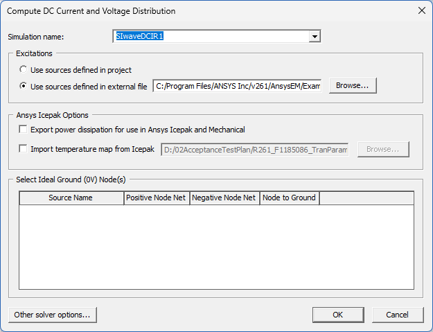
From the Compute DC Current and Voltage Distribution window, Use sources defined in external file is now selected and the adjacent field is populated with the path to the excitations source file.