
Geometry Command
The Fields Calculator Geometry command opens a dialog box for selecting a geometry to load into the top register of the calculator.
Do this to
- find the value of derived field quantities on any point, line, surface, or volume.
- plot quantities directly from the calculator.
- display a previously defined isosurface, maximum or minimum field point using the Draw command.
The following types of geometries are available:
|
Point |
See Drawing a Point
Object. Drawn points are listed |
|
Line |
See Drawing a Line
Segment or Drawing a 3D Line Segment. Drawn lines are listed
|
|
Surface |
Creatable Sheet objects and face selections Due to the ambiguity of the normal vector of a sheet, the result may require a multiplication by ( 1 ) or ( -1 ). If a Sheet object is selected from the face list, the dialog box also lists an Adjacent command that controls the side of the sheet on which the fields are calculated.
|
|
Volume |
3D objects, regions, and object selections (of 3D objects including AllObjects) are available in the calculator's Geometry dialog box when Volume is selected. |
|
Coord |
Coordinate systems are available in the calculator's Geometry dialog box when Coord is selected. |
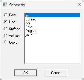
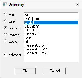

To load a geometry into the calculator:
- In the Fields Calculator, click Geometry.
The Geometry dialog box appears.
- Select a geometry type.
A list of all applicable geometries appears. If a design includes Layout Components, the Geometry list shows the available component geometries as well.
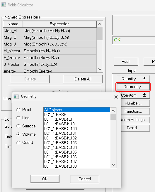
In the modeler window, these Layout Component objects are drawn as visualizations without actual geometry. However, they can be used to calculate field quantities as shown below.

These geometry operators can be used to perform computations just like one constructed from regular 3D geometry. These additional objects are generated only after reading a mesh, so they won’t show up if there is no solution.
- Click the geometry.
- Click OK to load the geometry.
Consider a box (Box2) that is completely enclosed in a bigger box (Box1), so that no faces of Box2 are touching any faces of Box1. Box2 is actually implicitly subtracted from Box1 as is done in our solvers. So Box1 is used as if Box2 were already subtracted from Box1. Volume(Box1) is Box1 excluding Box2, and Surface(Box1) contains faces from both Box1 and Box2.