
3D Modeler CAD Link
The 3D Modeler CAD Link allows you to create a User-Defined Model (UDM) from the geometry model in an Ansys Discovery project or in a supported third-party CAD project. In addition to Ansys Discovery, Ansys Electronics Desktop can link to models from NX, Solid Edge, Creo Parametric, Creo Elements/Direct, AutoCAD, and Inventor projects. The CAD link is only available on Windows.
For a list of supported CAD releases, see Geometry Interface Support.
The CAD link can only be used with Ansys Discovery if it is the same release version as Ansys Electronics Desktop and if both are installed on the same machine.
CAD Link provides following functionality:
- Browse and select CAD project files to import geometry directly.
- Import geometry by connecting to an active CAD session.
- The CAD geometry is imported as a UDM along with geometry parameters, rendering attributes and material assignments. For a Discovery model, the geometry parameters are imported with their units. Object, material, and parameter names with non-ASCII characters are not supported.
- If the design supports lightweight bodies, the normal "unfaceted" parts in the CAD model can be imported and faceted in Ansys Electronics Desktop with the specified facet level. For CAD software other than Discovery, the faceted parts cannot be imported. With a Discovery link, the faceted bodies can be imported directly, ignoring the specified facet level.
- CAD assemblies can be preserved if Create Groups for Sub assembly is checked in the 3D Modeler Options: CAD Link Options window.
- A CAD document referenced by a CAD link is included in the project archive automatically.
- You can break a CAD link. In this case, all the parts in the UDM are converted to imported objects.
Configuring Desktop for CAD Interfaces
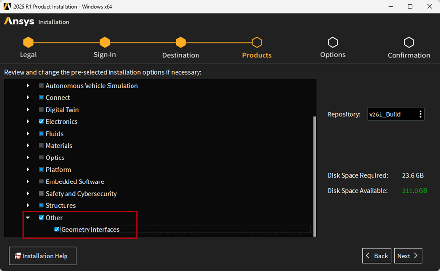
To use the CAD Link functionality, the Geometry Interfaces need to be installed and configured. The Geometry Interfaces can be found in the installer:
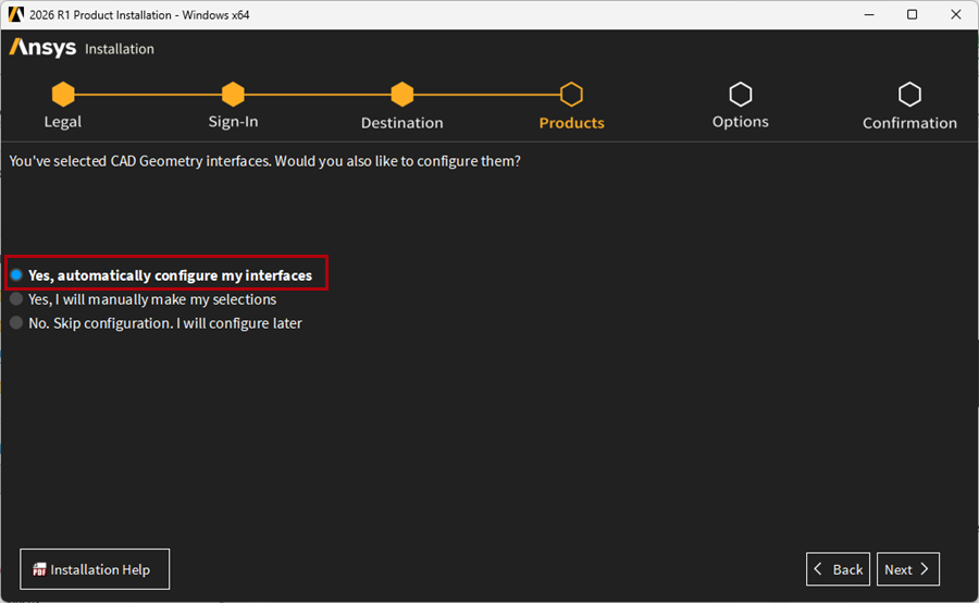
During installing, the Geometry Interfaces can be configured automatically:
If you did not configure the geometry interfaces during the install, you can use CAD Configuration Manager, which is accessible from the Ansys 2026 R1 Start menu.
Check each CAD program you will use, then select the Workbench Associative Interface option. Go to the CAD Configuration tab, and click Configure Selected CAD Interfaces.
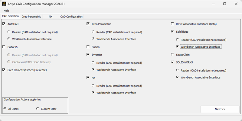
For more information on this functionality, see Using the CAD Configuration Manager.
Link CAD Geometry to Ansys Electronics Desktop
To select a CAD file:
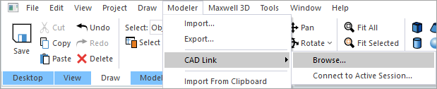
- Select Modeler > CAD Link > Browse or click the Browse CAD icon on the Model ribbon.
- Navigate to and select a project to load into the Modeler window.
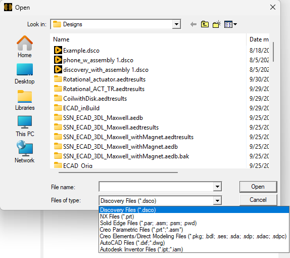
- Click Open.
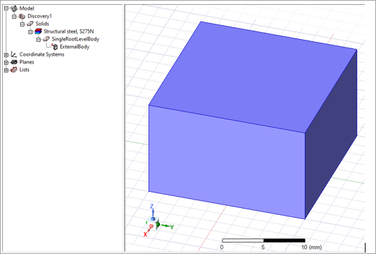
The progress bar displays import progress. When the model has loaded, it appears in the Modeler window, and in the history tree as a User-Defined Model (UDM) listed under the name of the CAD software. In the example below, a Discovery model was linked, so the UDM is labeled Discovery1.
The Files of Type field is not only for filtering the files, but also for specifying which CAD interface will be used. For the file extensions used by multiple CADs, for example,“.prt” is used by NX and Creo Parametric, make sure to select the correct file type according to the CAD interface used to generate that file.
If there is an active CAD session that is using the selected document, the created UDM will be linked to the active CAD session. If there is not one, a new non-graphical CAD session will be used, which makes the creating and refreshing slow. Afterward, if an active CAD session is launched and opens the document, the UDM will be linked to the active session.
To preserve assemblies from the CAD software as groups in Modeler, the Create Groups for Sub assembly must checked in the 3D Modeler > CAD Link options:
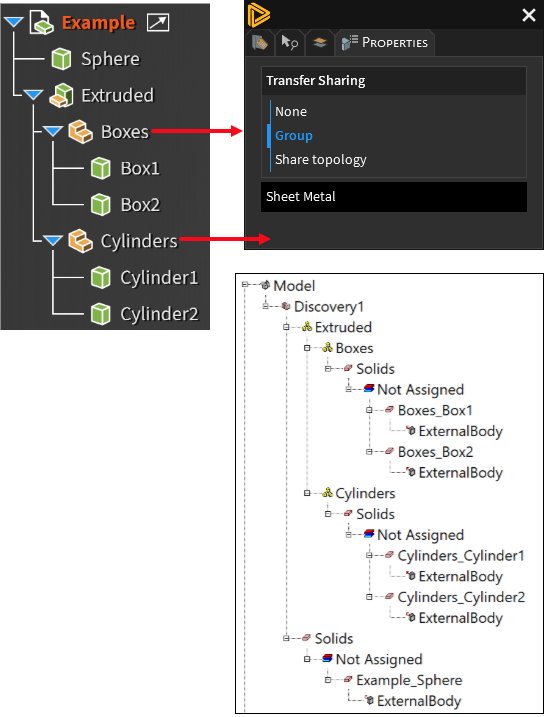
For Discovery, multi-body parts should have the Transfer Sharing property set to Group from within Discovery.
Note that group hierarchy is read-only, but individual parts of the CAD model can be duplicated or moved by right clicking on the part and selecting Edit > Duplicate or Edit > Arrange > Move, respectively.
Note that if the Import Named Selections option is checked in the Tools > Options > General Options > 3D Modeler > CAD Link window, named selections created in the CAD software will be listed in the Named Selections branch of the history tree:
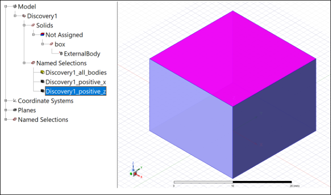
To synchronize imported named selections with the CAD software, right-click on the UDM (Discovery1 in the preceding example), and select Generate or Send Parameters and Generate. Within Ansys Electronic Desktop, the imported named selections cannot be directly modified or deleted without deleting the whole UDM.
Connecting to an Active CAD Session
If one or more CAD sessions are running on the machine, CAD Link can connect to them to import geometry.
When you select Modeler > CAD Link > Connect to Active Session or Connect to CAD in the Model ribbon, the Active CAD Sessions dialog box appears:
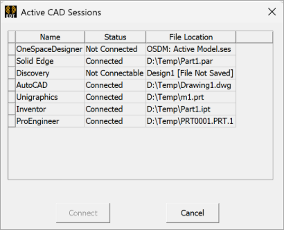
It shows all the CAD sessions that are currently running and detected by Ansys Electronics Desktop. The CAD software names that appear in this dialog box correspond to the names used in Ansys Workbench:
| CAD Software | Name shown in the dialog box |
|---|---|
| NX | Unigraphics |
| Solid Edge | Solid Edge |
| Creo Parametric | ProEngineer |
| Creo Elements/Direct | OneSpaceDesigner |
| AutoCAD | AutoCAD |
| Inventor | Inventor |
The Not Connectable Status indicates the CAD session does not have an active document or the document has not been saved. The exception is Creo Elements/Direct (OneSpaceDesigner), for which an active session can be connected without a saved document.
You can select a session and click Connect to import geometry from that session. Once connected, that session will be used to regenerate the corresponding CAD-linked UDM.
Note the following:
- NX does not support opening multiple files with the same name. If the connected NX file has the same name as an opened one in NX session, close the file before refreshing the CAD link.
-
Creo Parametric does not support opening multiple files with the same name. If the connected Creo file has the same name as an opened one in Creo session, close the file before refreshing the CAD link.
- CAD links to Creo Elements/Direct are connected to either an active session or a saved file. The source can be switched by changing the GeometryFilePath property of a created link (see Property Window of CAD-Link UDM). From active session to file, you can just input the file path. From file to active session, input the following: “OSDM: Active Model.ses”.
Preserving IDs During Parametric Variations
When a model is imported, IDs in Ansys Electronic Desktop depend on IDs available from the source CAD software. If parameters in the CAD software are set up such that changing their values causes existing parts to be edited, then IDs in the CAD software and Ansys Electronic Desktop remain constant across parametric variations.
However, if IDs in the source CAD change during a parametric update, then Ansys Electronic Desktop cannot match object/faces across variations. Ansys Electronic Desktop might delete original objects and create new objects, causing deletion of boundary conditions and failures in parametric simulations. Such a situation can commonly occur when an embedded script is used in the CAD software, and the script clears all parts at the beginning of script.
Named selections can be used in such situations to preserve IDs of objects/faces so that parametric simulations can proceed. In such cases, use the following guidelines:
- The total number of objects must be kept the same across parametric variations.
- If part IDs are changing in the CAD software, users must include every part in at least one object named selection and keep the name of each part constant across parametric variations.
- Discovery can have multiple parts with a same name. Ansys recommends assigning a unique name to every part and creating an object named selection that includes all parts in the model. If duplicate names cannot be avoided, then multiple named selections can be created so that parts with the same name are in different named selections. Ansys Electronic Desktop will match objects in a named selection by using their names and preserve IDs across parametric variations. This will preserve boundary conditions or other assignments in Ansys Electronic Desktop.
- If a named selection has a single face, then the ID of that face in Ansys Electronic Desktop will be kept constant across parametric variations even if it changes on CAD software side. If a named selection has multiple faces and the IDs of these faces change in the CAD software, then Ansys Electronic Desktop cannot guarantee that the ID of each face in that named selection will be preserved consistently. It is possible that IDs may switch among faces in that named selection. Ansys recommends creating a separate named selection for each face on which boundary/excitation is added in Ansys Electronic Desktop.
- If the number of faces in a named selection changes across parametric variations, then the face IDs may not remain constant.
Property Window of CAD-Link UDM
The Property window of a CAD-Link UDM has three tabs:
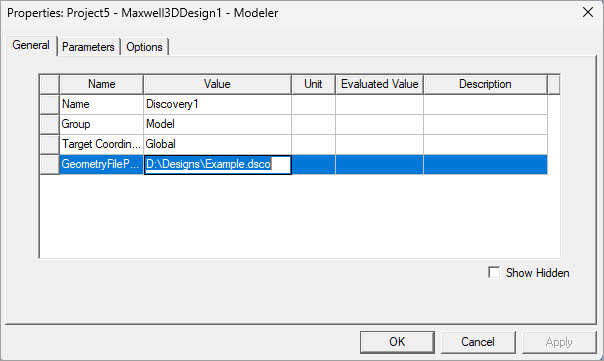
- The General tab shows general information such as CAD document path.
Note that the Geometry File Path is editable; users can update the path if the original file is moved.
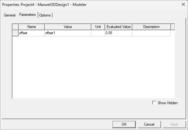
- The Parameters tab shows all parameters.
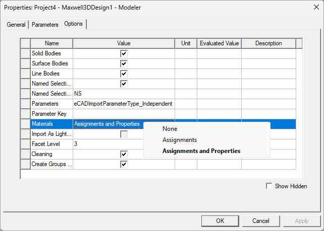
- The Options tab shows supported options. See 3D Modeler CAD Link Options for details on the options in this window. The example shown below is from a Discovery model.
You can edit the parameters and send them back to the CAD software to get the geometry updated accordingly.
After editing the parameter, you will need to use Send Parameters and Generate in the context menu of the CAD-linked UDM. If there is an active CAD session linked, its model will be updated, but not saved. If there is not an active CAD session linked, the CAD document will not be updated.
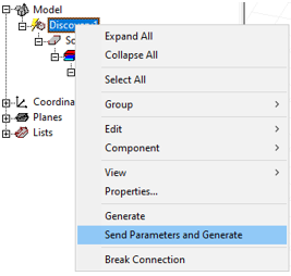
Note that parameter settings for an individual CAD model can be changed from this tab. After changing parameters, refresh the link by right-clicking and selecting Generate or Send Parameters and Generate.
Archive a Project Containing CAD Link
If you want to share a project with CAD link with other users, you need to archive the project, because the linked CAD file is not included in the project file. When archiving, the CAD documents corresponding to the links will be included in the project archive automatically. Once the archive file is unarchived, referenced CAD documents will be put in restored_files subfolder in the project directory. All definition paths are updated to refer to the reference files in restored_files folder.
An archived project only includes the linked CAD file. If the file is an assembly file that has links to other part files, you need to add them manually when archiving.
Break Connection with CAD Link
A Break Connection command is available in the context menu of the CAD link UDM.
- Break Connection converts the UDM bodies to imported objects. The UDM will be removed.
- Any operations that you have performed on UDM bodies are preserved.
- Parameters of the UDM are lost. You lose the ability to create parametric variations with the CAD model parameters.
- Attributes such as rendering attributes, materials, etc., are preserved.