Phasor Notation
Time varying quantities that have the form F(t) = Fmcos(ωt + θ) can be represented as rotating phasors in the complex plane.
Using Euler 's formula:
ejα = cosα + jsinα
Setting ωt + θ = α, F(t) equals the real portion of ej(ωt + θ):
F(t) = Fmcos(ωt + θ)
= ℜ [Fm(cos(ωt + θ) + jsin(ωt + θ))]
= ℜ [Fmej(ωt + θ)]
Each time-varying quantity now has the form Fmejωtejθ. The Fmejθ component is a complex constant that can be represented by a stationary phasor in the complex plane. The (Fmejθ)ejωt component is a complex number that depends on t, and can be represented as a rotating phasor in the complex plane, as shown in the following figure:
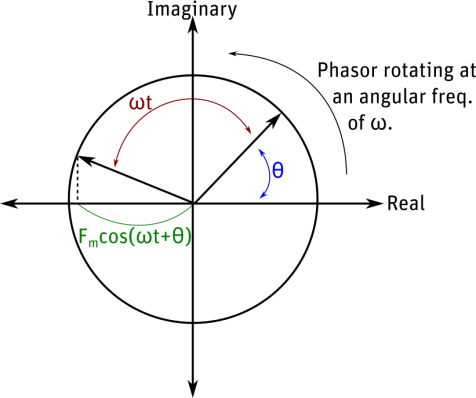
The phasor 's projection on the real axis oscillates sinusoidally. It reaches a peak when parallel with the real axis, and is zero when parallel with the imaginary axis. Therefore, a phasor with θ = 90° represents a quantity that peaks 90 degrees after a phasor with θ = 0°.
You need to enter magnitudes and phase angles when you specify voltages, currents and other boundary or source quantities in models where time-varying fields are computed (that is, AC Magnetic and AC conduction models).
Magnitude and phase angle are more readily handled in calculations when they are expressed in rectangular form (using the real and imaginary form x + jy) than in polar form (using magnitude and phase angle). Therefore, to specify currents and boundary conditions as functions you must describe them in terms of real and imaginary components.
The x + jy (rectangular) description of a phasor — [Fm(cos(ωt + θ) + jsin(ωt + θ))]— indicates that the phasor is the sum of two components: a sinusoid that peaks at ωt = 0°and a sinusoid that peaks at ωt = 90°.
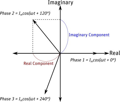
- The x component of the phasor is the real component and can be represented by a phasor that lies on the real axis of the complex plane.
- The y component is the imaginary component and is represented by a phasor that lies on the j-axis of the complex plane.
The real and imaginary components of the following three-phase system are related to the magnitude and phase of a sinusoid in this manner: