AC vs. DC Analysis
Q3D Extractor can compute resistance and inductance matrices for AC or DC problems.
AC Region
In the AC region, inductance is nearly constant with frequency. The AC self-inductance is lower than the DC inductance because skin effect reduces the magnetic fields (and the corresponding stored inductive energy) inside the conductors. Only the stored inductive energy in the region between conductors remains.
Resistance in the AC region increases proportionately with the square root of frequency. This occurs because the skin depth decreases with frequency, reducing the effective cross-section for current flow.
DC Region
In the DC region, resistance and inductance are both nearly constant with frequency.
Transition Region
Between the DC and AC regions of operation is a region that spans about 1 decade of frequency where neither the DC nor the AC models are truly valid. Here the skin depth is an appreciable fraction of the conductor depth. See: Estimating R and L Values in the Transition Region.
Frequency Ranges in AC Calculations
AC solvers compute high frequency asymptotes of inductance and resistance. While external inductance values do not grow with frequency, the resistance values are unbounded and increase with the square root of frequency. Therefore, the operating frequency must be specified to allow the software to calculate a finite resistance. The default operating frequency is 1 GHz. Alternatively, you can alter the frequency through matrix reduction. The skin depth used by the software is given by the following relationship (for reference, remember that the skin depth in copper (σ = 5.8 x 10⁷ S/m) at 1 GHz is 2.1 μm):
where:

- ω is the angular frequency, which is equal to
 (f is the frequency in hertz)
- σ is the conductor 's conductivity in S/m.
- μr is the conductor 's relative permeability. For most metals, μr = 1.
- μ0 is the permeability of free space,
which equals
 Wb/Am (or
  H/m).
H/m).
Thus, given a conductor with thickness d,
you can calculate the lower bound of the AC Region by calculating the
smallest frequency that produces a skin depth (δ) much smaller (say 3 times smaller) than
this thickness. Using the formula for d and the definition of  , you
have the frequency limit:
, you
have the frequency limit:

For copper, this reduces to f ≥ (0.04 Hz m2)/d2. For a 1 mm thick conductor, the AC inductance/resistance calculation is good for frequencies of 40 kHz or more. For a 100 μm thick conductor, the minimum frequency rises to 4 MHz, and so forth.
A similar calculation can be performed to determine the upper frequency bound for DC resistance and inductance calculations. By assuming that the skin depth must be greater than the conductor thickness d, the frequency becomes:

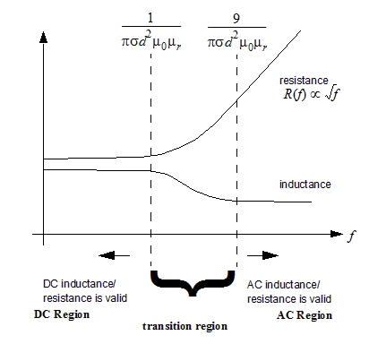
The following figure shows how typical circuit parameters vary according to frequency and illustrates the different frequency regions where the parameter calculations are valid: