
Setup Link (Convection)
When importing Non-Uniform film coefficient results from an Icepak design to a Convection boundary in a Mechanical – Thermal design, use the Setup Link dialog box to specify the source project, source design, and other linking options.
Imported film coefficients (also called HTCs, for Heat Transfer Coefficients) improve the accuracy of Mechanical – Thermal solutions, as compared to specifying a fixed film coefficient for each applied convection boundary. In Icepak, a fluid region surrounds the solid objects, and you specify various flow parameters, such as:
- Openings (flow inlet and outlet faces)
- Grills (openings with screens or perforations that partially inhibit the flow)
- Velocity of the fluid (for forced convection)
- Ambient pressure of the fluid
The remaining Icepak model setup involves specifying heat sources, selecting materials, and so on. The source Icepak model setup should duplicate the conditions, materials, and geometry in the target Mechanical design, except that a fluid region surrounds the solid parts in the Icepak design. A fluid-thermal multiphysics analysis is performed. Fluid motion can be driven by natural convection (buoyancy) alone, specified fluid velocities, or a combination of both. Fluid velocities are calculated along with the resultant HTCs at each element face. A face's HTC increases as the fluid velocity along the face increases.
Refer to the Icepak help for more information.
- The Mechanical design objects that represent heat sources, and those with convection boundaries applied, should have geometrically identical counterparts in the Icepak design. Coefficients are mapped according to the locations of the element faces. Identical geometry ensures that mapping of film coefficients from source element faces to target element faces is performed successfully and accurately. Additionally, the surface mesh size should be similar between the two designs. Though Icepak element faces are quadrilateral, and Mechanical faces triangular, the mapping results will be good if the element lengths are comparable.
- The fluid region in the Icepak design must be omitted from the Mechanical - Thermal design. The convection boundary alone produces the heat exchange between the solid objects and the ambient environment. A fluid region around the parts would represent an additional path for the conduction of heat and would skew the Mechanical – Thermal results.
- In the Icepak solution setup, and when assigning a Thermal Source in Icepak (analogous to a Heat Generation or Heat Flux excitation in Mechanical – Thermal), you have the option of enabling Radiation effects. If you do so, the HTCs imported from Icepak will include the effects of both convection and radiation, not just convective heat transfer alone.
- Radiation is very nonlinear, varying according to the difference between the fourth power of the absolute temperature at each surface (T14 ‑ T24). It therefore becomes increasingly significant as the surface temperatures increase. At relatively low surface temperatures, radiation effects are not very significant, as compared to forced convection. However, for natural convection, the contribution of radiation is usually significant.
- The link between Icepak and Mechanical is a one-way coupling operation. Changes you make in the target Mechanical design have no effect on the source Icepak design's results.
- Mechanical design changes involving the specified ambient temperature, applied power (heat generation, heat flux, or EM loss), applied temperatures, or anything that changes the temperature results (such as material properties) may significantly affect the validity of the imported HTC values from Icepak. This relationship is true under either of the following two conditions:
- Fluid motion is driven by buoyancy alone (that is, by natural convection), or
- You are including radiation effects in Icepak (whether the fluid flow is by natural or forced convection)
In such cases, you should consider revising and rerunning the Icepak analysis to keep the two models consistent and to update the HTC values. Then, rerun the Mechanical – Thermal simulation to see the effects of the revised HTC values.
However, when forced convection is employed and radiation is not included, the HTCs do not change significantly with variations in temperature. In this case, you can safely run multiple Mechanical – Thermal analyses based on imported HTCs from a single Icepak solution.
How to Set Up the Icepak Link
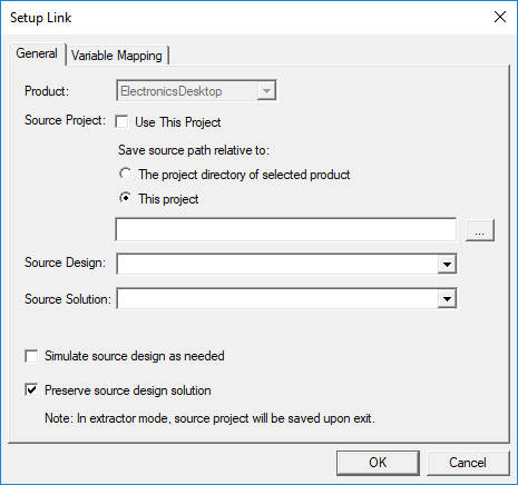
- Follow steps 1 through 3 of the How to Assign a Convection Boundary procedure, selecting the Non-Uniform option in the third step. The Setup Link dialog box appears:
- If the data is to be imported from an Icepak design in the same project, complete the following substeps. Otherwise go to step 3:
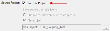
- Select Use This Project.
- Skip to step 4.
- Alternatively, if the data is to be imported from an Icepak design in a different project, clear the Use This Project option and complete the following substeps:
- The Mechanical design saves the relative path to the source project in one of two ways. Choose one of the following two options under Save source path relative to:
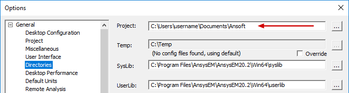
- The project directory of selected product: Save source project path relative to the default Project folder specified in the Options dialog box (Tools > Options > General Options):
- This project: Save source project path relative to the target project location.
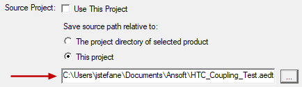
- Click the ellipsis button ( ... ) to the right of the Source Project text box.
- Locate the source project file and select it.
- Click Open
- Choose the Source Design and Source Solution from the provided drop-down menus:
- Optionally, select one or both of the following two options:
- Simulate source design as needed: Select this option if you want an updated solution to be linked to the target design when the source design has been modified.
- Preserve design solution: When the source design is in a separate project, and that project is closed, the source design will not be saved (preserving the preexisting solution data). This option has no effect if the source design is in the same project as the target design.
- Click the Variable Mapping tab.
- Optionally, to keep the source and target design variables synchronized, click Map Variable by Name. Then, the same variable names will appear in both columns, and the values will remain synchronized between the linked analyses.
- Variables can only be mapped by name if they already exist in the Mechanical design. When you copy and paste geometry from the source, or import it from the clipboard, variables used in the definition of the geometry automatically come into the Mechanical design. However, for non-geometry-related variables (such as a wattage applied to a thermal source excitation in the Icepak design), you would have to manually define the variable within the Mechanical design.
- When the Value Mapped to Source Design column contains constants, those constant values will be passed to the source design even if you change the associated variable's value in the target design's Properties dialog box (Mechanical > Design Properties) or in the docked Properties window (with the target design selected in the Project Manager).
- If you have not mapped the detected variables by name, you will be prompted with a warning upon attempting to close the Setup Link dialog box. The warning will allow you to return to the Variables Mapping tab to click the Map Variable by Name button. Alternatively, you can accept the unsynchronized variables and close the dialog box.
- Click OK to accept the link settings and close the Setup Link dialog box.
- Continue the convection boundary setup at step 4 of the Convection topic.
It is convenient to include source and target designs within the same project. Doing so keeps all project files in the same location and is the most convenient and straightforward way to organize linked designs. However, this approach may be impractical when there is a large number of designs in the project.
The Open dialog box appears.
The selected Source Project is listed in the Setup Link dialog box:
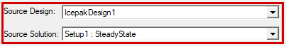
These two settings are automatically populated with an available design and solution in the source project. However, if more than one other design or solution exists in the source project, you can manually select the desired ones (if different from the automatically selected design or solution).
If design variables have been defined in the source design, they are listed in the Variable from Source Design column. Initially, the nominal value of each variable is listed in the Value Mapped to Source Design column:
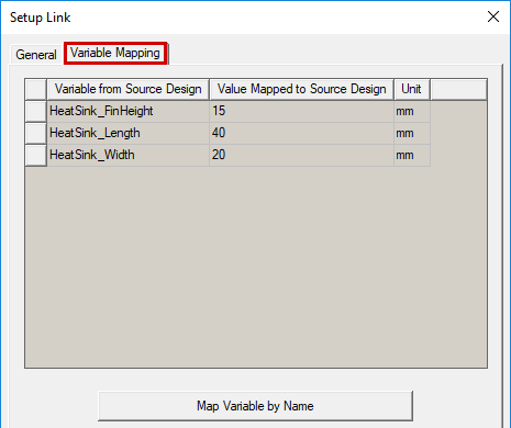
The values passed back to the source design from the mechanical design (second column) can either be constants (numeric values), variables, or expressions. The specified values determine the variation from which the source design provides the linked data.
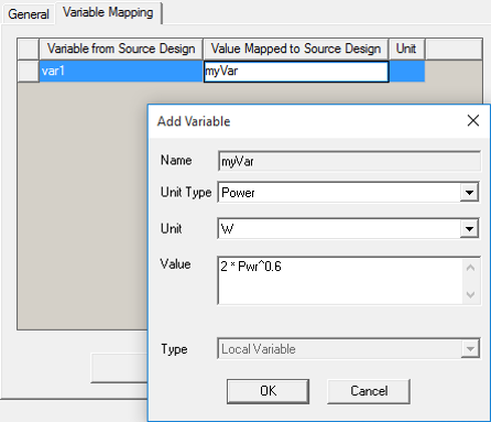
Automatic variable creation is supported in the Variable Mapping tab . You can directly type a new variable name into the Value Mapped to Source Design column, and the Add Variable dialog box will appear, in which you can define the Units and Value of the variable. The specified value can be a constant, a variable name, or an expression.
.png)
Mapping variables to the source design by name is useful for Optimetrics analyses (for cases where changing the value of a variable affects both the target design and the film coefficients from the source design). You can create an Optimetrics setup in the target design that sweeps both the target and source designs.
If you later revisit the Convection dialog box to verify or modify its properties, click the Setup Link button under the General tab to return to the Setup Link dialog box. This dialog box will reopen in View Only mode. To modify the properties, first select the Edit Link radio button.