
TAU 2D Mesh Generation for Rotational Models
If the mesher determines that a model is a rotational model, it uses a rotational mesh generation with either the clone mesh or rotational sweep mesh method.
To determine if the model is a rotational model, the curves around the origin are calculated. The smallest rotational gap is defined as the “Band” gap. The model shown below is an example of a rotational transient model:
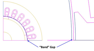
Two major regions, a static region and a moving region, are classified by the Band gap.
TAU 2D Clone Mesh Generation
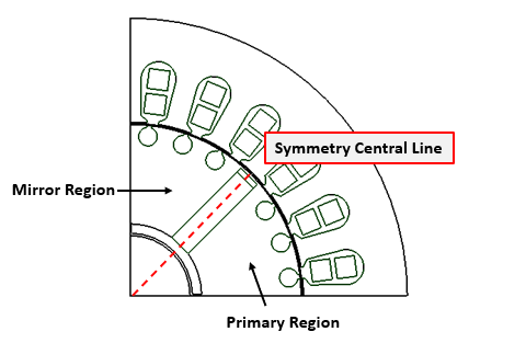
The static geometric model in the local rotational region is analyzed to determine whether it has duplicate subregions. If a model has duplicate subregions, the TAU clone meshing is automatically activated and will generate the mesh so that each subregion has the topologically identical mesh. The following example shows a static clone region with six identical subregions - a master and clone regions:
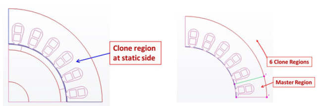
In the clone region, the master region is calculated and analyzed. If the master region has a symmetric feature, the symmetric mesh is generated; see Maxwell 2D Symmetry Mesh below.
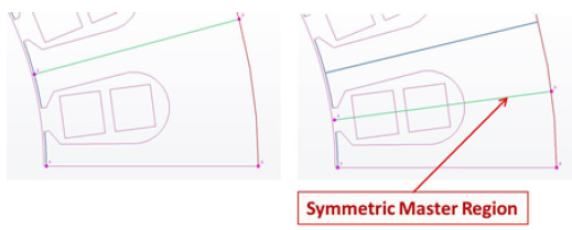
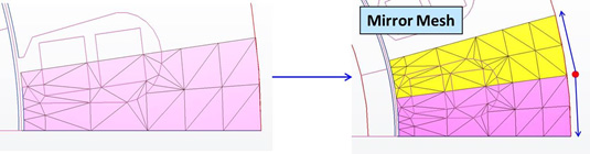
As shown above, a uniform mesh will be generated in one half of the master region first, then the mesh is mirrored about the symmetric central line to generate the symmetric mesh in the master region.
Because all the child regions have identical geometric features, the mesher uses copy-paste to replicate the master mesh at each of the child regions, rotating it to the appropriate angles.
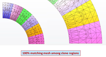
This ensures the identical mesh in the different regions, especially for the teeth.
TAU 2D Rotational Sweep Mesh Generation
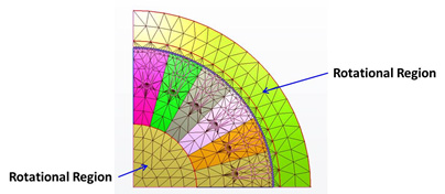
If the local region does not have identical geometric subregions and thus the clone mesh is not generated, a geometric analysis is performed to verify whether the region is rotational.
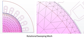
Around the rotational center, if a region has two or more rotational curves, this region can be defined as a “rotational” region. In this case, rotational sweep mesh generation is used proceeding in the radial direction with layers while using uniform sweep elements in the rotational direction. This meshing method controls the aspect ratio in the radial direction, while maintaining the uniform sweep in the rotational direction.
Maxwell 2D Symmetry Mesh
A symmetry pattern is characterized by the existence of a symmetry central line. The objects/outlines at one side of the symmetry central line can be constructed mirroring the objects/outlines at the other side of the symmetry line:
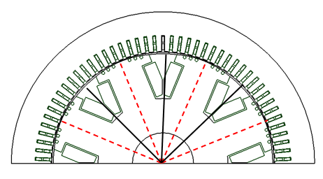
A specific geometry can be a combination of a mirror and a circular pattern. For example, in the transient simulation of motors, the design may contain one or multiple symmetry patterns, as shown below:
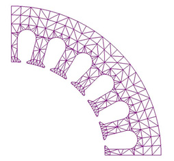
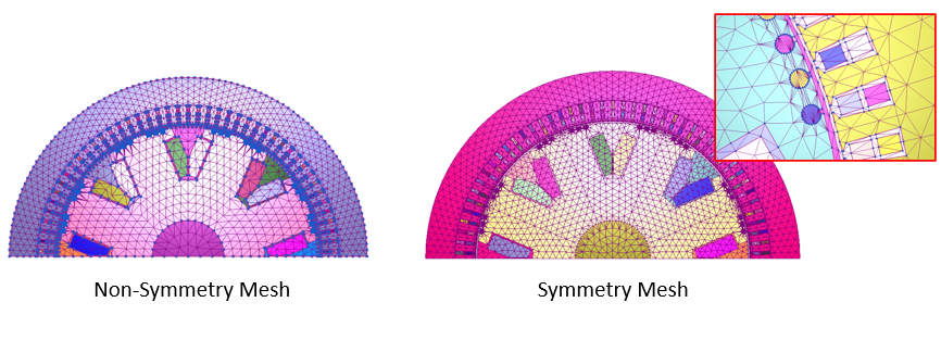
The TAU mesher will automatically detect such patterns regarding their inner symmetry and their circular periodicity. It will then create a symmetric and periodic mesh to reduce simulation noise. The resulting mesh can be plotted to verify its symmetry:
Symmetry mesh can be combined with mesh density control when this mesh operation is applied to the initial mesh.
Note the following:
-
To generate a symmetry mesh, the band of motion must be defined using a curved, i.e., non-segmented, object such as an unsegmented circle with one outer edge.
-
In addition to (1), no segmented outlines should be defined around the band (e.g., inner region object). If required, these objects should also be defined by unsegmented, curved geometry.
-
Symmetry mesh is currently not compatible with a band mapping angle mesh.