Assigning Boundaries and Excitations for 3D Designs
For every project, you need to assign boundaries and excitations. For 3D designs, you can use the Maxwell 3D menu or the project tree to do the following:
- Define boundary conditions that control how the electric or magnetic field behaves at object faces, planes of symmetry and periodicity, and edges of the problem region.
- Define excitations of voltage, charge, coil, and current.
- Identify conductors in which eddy currents are induced.
- For AC magnetic and magnetic transient projects, set up a winding and an external circuit connection.
Each field solver requires you to specify excitations of electric or magnetic fields and references for computing these fields.
- Magnetostatic Boundaries and Excitations
- AC Magnetic (Eddy Current) T-Omega Boundaries and Excitations
- AC Magnetic (Eddy Current) A-Phi Boundaries and Excitations
- Transient Boundaries and Excitations
- Transient A-Phi Formulation Boundaries and Excitations
- Electrostatic Boundaries and Excitations
- DC Conduction Boundaries and Excitations
- Electric Transient Boundaries and Excitations
- AC Conduction Boundaries and Excitations
You must specify at least one of the boundary conditions or excitations listed in these sections, so that the simulator can compute accurate values for fields and parameters.
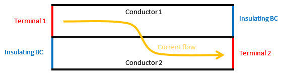
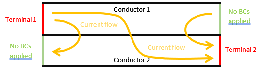
Depending on the problem to be solved, you must also define the current flowing through the conducting domain faces touching the domain boundaries (ports) by assigning them excitations or setting their current to zero by defining insulating boundary conditions. If no constraint is applied to that boundary, the current will flow freely through these ports, which may lead to undesired but still physical results.
Case 1: Conducting faces without boundary conditions (BCs) applied (green lines). The current flows freely through these faces.
Case 2: Insulating boundary conditions applied (blue lines). No current is allowed to flow through these faces.