
Bondwire Definitions
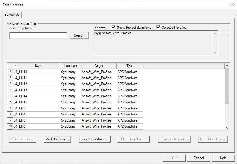
To view a list of bondwire definitions, on the menu bar click Tools > Edit libraries > Bondwires to open the Bondwires tab of the Edit Libraries window. From this window, add, edit, import, clone, remove, or export a bondwire definition.
Add a Bondwire Definition
- Click Add Bondwire to open the New Bondwire Definition window.
- Optionally, enter a new name for the definition to replace the default.
- From the Type field, select a type of bondwire profile definition.
- Click OK to open the Bondwire Definitions window with default values.
- For APD PrimBondwire Definitions:
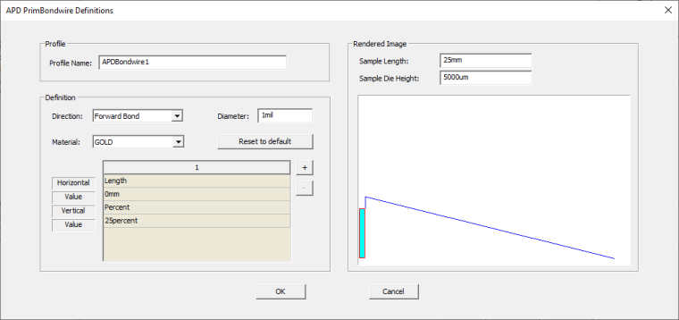
- Select a Direction.
- Enter a Diameter with its units.
- Choose a Material.
- Select Edit to open the Materials tab of the Select Definition window.
- To add a segment, click + and adjust the segment’s settings. All the changes are reflected in the bondwire graphic.
- To remove a segment, the number of the segment and click –.
- Click OK.
- For JEDEC4 Prim Bondwire Definitions:
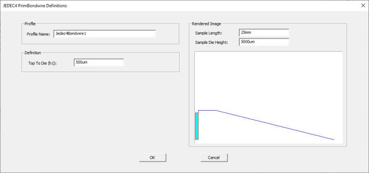
- Enter the height from Top to Die including its unit of length. This is the height between the bond pad and the top of the loop.
- Click OK.
- For JEDEC5 PrimBondwire Definitions:
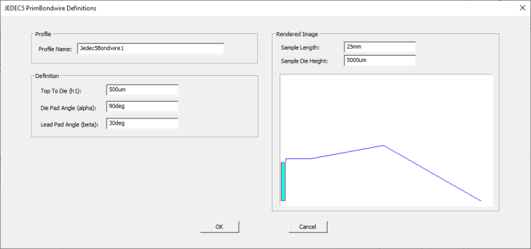
- Enter the height from Top to Die including its unit of length. This is the height between the bond pad and the top of the loop.
- Enter the Die Pad Angle which is the angle between the horizontal plane and the wire at the bond pad point. Include the unit deg.
- Enter the Lead Pad Angle which is the angle between the horizontal plane and the wire at the lead point. Include the unit deg.
- Click OK.
Editing a Bondwire Definition
- Select the profile definition you want to edit and click Edit Bondwire to open th Bondwire Definitions window.
- For APD PrimBondwire Definitions:
- Choose a Direction.
- Enter a Diameter with its units.
- Choose a Material.
- Select Edit to open the Materials tab of the Select Definition window.
- To add a segment, click + and adjust the segment’s settings. All the changes are reflected in the bondwire graphic .
- To remove a segment, the number of the segment and click –.
- Click OK.
- For JEDEC4 Prim Bondwire Definitions:
- Enter the height from Top to Die including its unit of length. This is the height between the bond pad and the top of the loop.
- Click OK.
- For JEDEC5 PrimBondwire Definitions:
- Enter the height from Top to Die including its unit of length. This is the height between the bond pad and the top of the loop.
- Enter the Die Pad Angle which is the angle between the horizontal plane and the wire at the bond pad point. Include the unit deg.
- Enter the Lead Pad Angle which is the angle between the horizontal plane and the wire at the lead point. Include the unit deg.
- Click OK.
Importing Cadence Bondwire Profiles
- Click Import Bondwire to open an explorer window.
- Navigate to and select a Cadence XML wirebond type definition files
- Click OK.
Cloning a Bondwire Definition
- From the grid, select a bondwire definition to clone.
- Click Clone Bondwire. The Bondwire Definitions window opens with values identical to the selected definition.
- Click OK.
Removing a Bondwire Definition
- From the grid, select a bondwire definition to delete. Only project definitions can be deleted.
- Click Remove Bondwire.
- Confirm the removal. The definition is deleted on the grid.
Export Bondwire Definitions to File
- From the grid, select a bondwire definition to export. Only project definitions can be exported.
- Click Export To Library.
- From the Export to Library window, navigate to where you want the file to go and click Save.
- Confirm the export.