
The HFSS 3D Modeling GUI
The following illustration shows the HFSS 3D modeling graphical user interface (GUI) of the Ansys Electronics Desktop application and some elements and windows that appear on it. These elements, which include controls and commands, are presented in various graphical forms, such as menus, ribbon tabs, dialog boxes, etc.
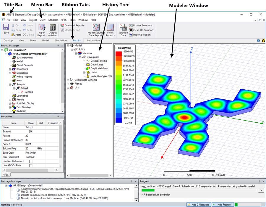
HFSS GUI
The Menu Bar is located near the top of the GUI. It consist of a group of menu commands arranged by category such as File, Edit, Project, Draw, Modeler, HFSS, Tools, etc. The Ribbon contains frequently used commands arranged into Tabs of logically related functions such as View, Draw, Model, Simulation, Results, and more. Commands for all operations in HFSS are accessible from the items and buttons in the menus and ribbon tabs. You can also right-click in the appropriate window or on Project Manager entries to perform desired operations.
For example, to excite a design with a wave port, select the appropriate face on the design, click the HFSS menu, go to Excitations> Assign > and click Wave Port. This command brings up the wave port wizard where you can enter the settings to apply the wave port excitation.
Alternatively, select the appropriate face on the design, right-click in the Modeler window, select Assign Excitation and click Wave Port from the shortcut menu.
There are six distinct windows that can be active within the HFSS GUI:
- Project Manager
- History Tree
- Modeler
- Properties
- Message Manager
- Progress
Each of the windows serves a unique purpose during the creation and simulation of a given HFSS design.