
Primary and Secondary Boundaries
Primary and secondary boundaries (Lattice Pairs) enable you to model planes of periodicity where the E-field on one surface matches the E-field on another to within a phase difference. They force the E-field at each point on the secondary boundary match the E-field to within a phase difference at each corresponding point on the primary boundary. They are useful for simulating devices such as infinite arrays.
Unlike symmetry boundaries, E does not have to be tangential or normal to these boundaries. The only condition is that the fields on the two boundaries must have the same magnitude and direction (or the same magnitude and opposite directions).
When creating matching boundaries, keep the following points in mind:
- Primary and secondary boundaries can only be assigned to planar surfaces. These may be the faces of 2D or 3D objects.
- The geometry of the surface on one boundary must match the geometry on the surface of the other boundary. For example, if the primary is a rectangular surface, the secondary must be a rectangular surface of the same size.
- If the mesh on the primary boundary does not match the mesh on the secondary boundary exactly, the solution will fail. Normally HFSS automatically forces the mesh to match on each boundary; however, in some cases, the mesh cannot be forced to match. To prevent the solution from failing, create a virtual object on the secondary boundary that exactly matches any extra object on the primary boundary, or create a virtual object on the primary boundary that exactly matches any extra object on the secondary boundary.
- To make a surface a primary or secondary boundary, you must specify a coordinate system that defines the plane on which the selected surface exists. When HFSS attempts to match the two boundaries, the two coordinate systems must also match each other. If they do not, HFSS will transpose the secondary boundary to match the primary boundary. When doing this, the surface to which the secondary boundary is assigned is also transposed. If, after doing this, the two surfaces do not occupy the same position relative to their combined defined coordinate system, an error message appears.
For example, consider the following figure:
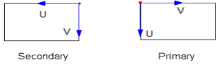
To match the coordinate system of the primary boundary, the coordinate system on the secondary boundary must rotate 90 degrees counterclockwise; however, when this is done, you get the following:
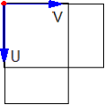
The two surfaces do not correspond and thus the mesh will not match, causing an error message.
- The angle between the axes defined by the u point and v point must be identical for the primary and secondary boundary.