
Port Options
If the design includes wave ports, the Port Options appear under the Advanced options tab of the Solution Setup dialog box.
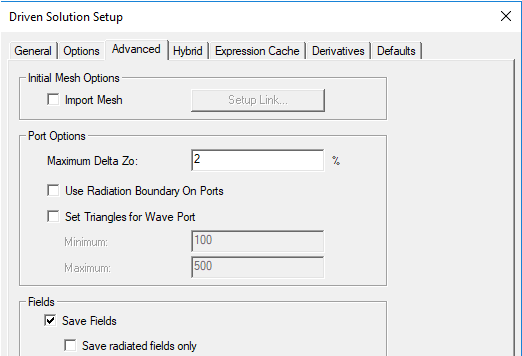
These options include:
- Maximum Delta Zo - change to Zo specified as a target percentage. The default is 2%. The port solver computes mode patterns and propagation constants based on solutions of a finite element system of equations. The finite element mesh associated with each port is a 2D mesh of triangles corresponding to the faces of the tetrahedra that lie on the planar port surface. The port solver performs an iterative refinement of the triangular mesh. During the port solve a 2D adaptive process analogous to the well known 3D process is employed to determine the fields for the port. As we have a max delta S for the overall 3D solution, on the port the convergence criteria is tracking the port impedance, Zo, as a function of these rapid 2D passes to the port. For a technical explanation, see Mesh Refinement on Ports.
- Use Radiation Boundaries on Ports
- Set Triangles for Wave Port - unchecked by default.
If you check Set Triangles for Wave Port, the Minimum and Maximum fields are enabled. You can edit the default values of 100 for the minimum and 500 for the maximum.
For designs with lumped ports, this option is not active. Higher numbers of triangles would not benefit a solution setup in this case.
Beta Option: Enhanced Tau Port Meshing
The port solver requires an all planar mesh on ports. If the ports overlap with other objects or faces, occasionally the initial mesher may generate a non-planar mesh or an inaccurate mesh and then the port solver will fail or rejects the mesh. In such situation, you may need to use this Beta feature for accurate port mesh.
It uses a two stage approach to mesh generation. In stage-1, mesh on all the ports or user specified “high priority surface representation” faces will be generated, and strict mesh verification will be applied. Repair methods are involved if an inaccurate port mesh is found. This ensures that a satisfactory port solver driven mesh is created. Then in stage-2, all the remaining objects will be placed to the pool for the mesh. When an overlap or tiny gap is found, these faces will be treated as lower priority objects compared to ports.
Technical Notes: Port Solutions