Mesh Fusion
With mesh fusion you can specify that multiple design modal FEM components and native regions are meshed independently to ensure very robust and rapid meshing. If a design contains multiple instances of a component, that component need only be meshed once. Parametric variations for one or more instances only affects the mesh of those instances. You can access the Do Mesh Fusion dialog through the Project tree shortcut menu for 3D Components, using the Set Components for Mesh Fusion... command. You can use the dialog to manage settings for all components in the project.
The solver supports mesh fusion for FEM volume and HFSS 3D Layout components in HFSS design type. This type of volume component cannot coexist with any FEBI, and/or surface and/or SBR+ components. Similar to 3D components, HFSS 3D layout components, when marked as mesh fusion, also support mesh envelope padding and mesh setting override. The mesh setting override dialog for layout components are different from that for 3D components and can be seen in the figure below.
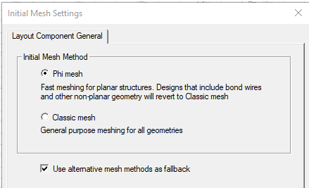
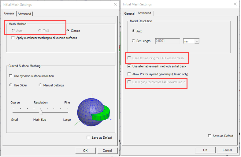
In this dialog, you can choose different mesh methods specific to layout components. This dialog is fully modeless, which loads different pages when you select layout or 3D components. In addition to this dialog, the Initial Mesh Setting dialog for the native design is also modified. If there are layout components meshed in native, the Initial Mesh Setting dialog will disable the Auto and TAU mesh method. The options related to TAU in the advanced setting page are also disabled.
With the proper setting, the design can be meshed and solved. Layout components marked as mesh fusion will have full interaction with other layout components, 3D components and native geometry.
Some of the benefits of Mesh Fusion are as follows:
- Systems with large variation in length scales can be successfully meshed. For example, in the case of a small 3D antenna touching an aircraft, you can mesh both the bodies separately and ensure a conformal mesh between them. That is, the triangulations in the contact area between the volume mesh of the 3D antenna component and the surface mesh of the aircraft are aligned resulting in a conformal mesh.
- You can select different meshers for each component via the Component Meshing properties, or directly . That is, you can pick the Tau mesher for a given component and the Classic mesher for another component, in order to ensure system meshing is successful.
- The iterative solver option is available for mesh fusion projects as an Advanced Solution Setup option, except for 3D component array in both 3D layout and MCAD. The Iterative solver uses 1.e-6 as the default.
- Faster meshing for multiple instances of the same component is possible: only one initial mesh is created. For instance, when multiple identical antennas appear in a design, only one needs to be meshed.
- Mesh resuse enables fast placement studies. If you move a component, no re-meshing needs to be done. Also only the last adaptive mesh is used and no adaptive meshing of the component needs to done.
- Reused initial meshes are not impacted by any parametric variation. Suppose there are multiple components that are independently meshed and you make a parametric variation in one component, the remaining components are not remeshed. In this situation, the last adaptive mesh cannot be reused. Some examples of parametric variation can include increasing or decreasing the dimension of a geometry or changing the material properties.
- Mesh fusion can be distributed, including support for distributing Iterative Solver Excitations.
-
Mesh Fusion components can be marked as Priority in the Mesh Fusion Settings dialog box. It is common for a large project to have some native objects intersect with mesh fusion components due to user error or modeling issue. These intersections are usually small and would not affect simulation result if ignored, but they can stop simulations and cost much time to fix. To improve this problem, you can mark any mesh fusion components as priority.
The dialog also contains a section to enable Priority Level ranked from Highest to Lowest for each component in the design. This feature aims to develop a better intersection resolution mechanism that could help you resolve most of the intersections with ease and customization for both regular and mesh fusion applications.
Once the Priority Level is enabled, a column named “Priority Level” replaces the “Priority” column. In this setting, all the components in the design are ranked from highest priority to the lowest based on rules for default priority. You can drag a row to change the priority level of a component. Alternatively, you can also click the cell in the Priority Level column for a row to open a drop-down list. You can then pick a level in the list and assign it to that component.
Additionally, you can click the Reset to Default button to assign a default priority level to all components. For details on how the default priority is calculated, refer to the Rules for Default Priority section below.
Most of the intersections will be resolved automatically during simulation according to the priority levels. All the resolutions will happen behind the scenes, and you will not notice any difference due to objects being cut-off in the post processing. This priority levels setting is only used for resolving intersections and not for containment. This priority levels setting will enforce the material setting to turn on.
Once you enable Priority Level, the design validation reports the intersection resolution result.
If the priority levels setting is not enabled, HFSS uses the old behavior to handle any intersections.
Rules for Ranked Priority Level
If you enable Priority level and use the default rankings the rules for Default Priority Level apply.
Rules for Default Priority Level
Default Priority level uses the following rules.
-
Starting from the first rule, the dialog applies each rule to compare the priority levels of two components until the winner can be determined.
-
Components that are checked for mesh fusion have higher priority than those that are not.
-
Layout/encrypted 3D components have higher priority than regular 3D components.
-
If both components are checked for mesh fusion, the component with smaller mesh envelop has higher priority.
-
If both components are not checked for mesh fusion, the component that is inserted later has higher priority.
-
Geometries that do not belong to a component have the lowest priority.
Rules for Resolving Intersection between Two Objects
If two objects intersect, and the priority level is enabled, HFSS tries to resolve the intersection using the following rules. Starting from the first rule, HFSS applies each rule until the winner can be determined.
-
If one object is conductor and the other object is dielectrics, conductor wins in the region of intersection.
-
If both objects are conductors or dielectrics, the object that belongs to the component with higher priority wins.
-
If both objects are conductors or dielectrics and have the same component priority level, but their material is different, it is not valid. The code will return validation error.
-
For the rest of the case, the object with the smaller volume wins. If their volumes are equal, the object with smaller ID wins.
For example:
Two objects, red and blue, intersect. Both are conductors. The program determines that the red object has higher priority according to the rules.

The red object will take precedence in the region of intersection.

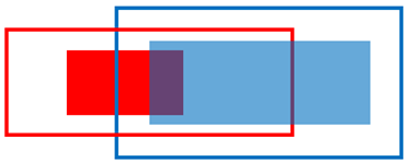
Rules for Resolving Intersection between Two Components’ Mesh Fusion Envelope
If two components are marked as mesh fusion, and their mesh envelopes intersect, the envelope that belongs to the component with higher priority level takes precedence in the region of intersection. The intersecting portion is subtracted from the envelope with lower priority. The mesh fusion envelope includes both the user defined mesh region and auto-generated mesh envelope.
For example:
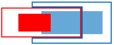
There are 2 components in red and blue. The rectangular outline represents the mesh fusion envelop of each component, and the solid rectangle represents the actual geometry of that component. The two components’ mesh fusion envelopes intersect, and the red component has a higher priority level.

HFSS resolves such intersection by subtracting the intersecting portion from the blue component’s mesh fusion envelope.

Rules for Resolving Intersection between an Object and Another Component’s Mesh Fusion Envelope
If one object intersects another component’s mesh fusion envelope, the intersecting portion is cut off from the object and included with the other component. This cutout portion is meshed with that component.
If there are any boundaries or mesh operations assigned on the object, they are shared to the cutout portion. However, the following case is not valid and will cause a validation error.
-
The object belongs to a layout component or an encrypted 3D component
-
The cutout portion is assigned with circuit elements or excitations
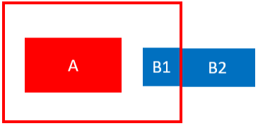
For example:
There is a component A whose mesh fusion envelope intersects with object B.
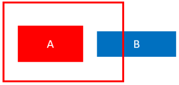
The intersecting portion is cut off from Object B. Object B is now split into 2 parts, B1 and B2. B1 is meshed with component A.
Putting it all together:
In the below example, there are 2 components in red and blue. The rectangular outline represents the mesh fusion envelop of each component, and the solid rectangle represents the actual geometry of that component. The two components’ mesh fusion envelopes intersect, so do their actual objects. The red component has a higher priority level.
The envelope-envelope intersection is resolved by subtracting the blue component’s envelope. After this, the blue component’s envelope no longer intersects with the red component’s actual object. However, the red component’s envelope still intersects with the blue component’s actual object. This intersection is resolved by cutting off the intersecting portion from the blue object and including it with the red component.
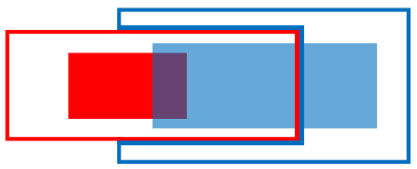
The cutout portion from the blue object still intersects with the red component’s actual object. This intersection is resolved by letting the red object take precedence in the region of intersection.
With all the intersection resolved, the two components are processed and split into two new groups of geometries that are meshed separately using mesh fusion.

On the other hand, if the blue component has higher priority instead, the two components will become the following after intersection resolution.

Rules to Resolve Containments
The Priority Level feature does not introduce any new rules to resolve the case in which one object contains another object. HFSS follows the old behavior for resolving such containment or reporting error. However, the Priority Level feature resolves a special containment case in which one component’s mesh fusion envelope contains another component’s mesh fusion envelope. This case was invalid in prior releases but can now be supported by letting the smaller envelope subtract the larger envelope. This leaves a cavity on the larger envelope, and the smaller envelope resides in the cavity.
Rules for Simple Priority
Using Simple Priority, if a priority mesh fusion component intersects a native object, the intersecting portion is subtracted from the native object, so that the simulation continues.
-
-
If the intersection portion has boundary assignment, the simulation will still report error
-
If two mesh fusion components intersect each other, the simulation will still report error
-
Any overriding mesh setting appears in each component’s property window.
-
Mesh Fusion can share surface approximation operation between imprint face pairs that have curved outlines. Take surface approximations assigned on face, on body, and on the component level for both faces of the imprint pair and combine them to create the operation that results in finest mesh. This will only be done for face pairs that have classic mesh method on both sides. (TAU mesher does not support assigning surf approximation on planar faces, even if they have curved edges.) You can automatically assign 15 degrees normal angle to all shared mesh operations by env var ASSIGN_15_DEG_NORMAL_DEV_TO_CURVE_IMPRINT. This approach does not support array in native.
-
You can generate field plots using data from either side of the boundary surfaces, using the “Adjacent side” check box on the Field Plot dialog, despite the sides belonging to different meshes and domains.
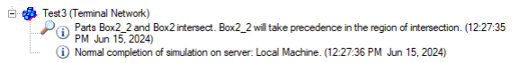
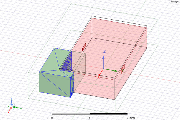
Layout components that are marked as Mesh Fusion also support the priority option. The priority option provides a way to resolve component intersection conflicts with native objects. If such intersection appears, the intersecting portion will be subtracted from the native object, so that the components marked as priority stay intact and the simulation could continue. For example, consider a design with layout component being intersected by a native box.
If the priority option is not marked for this layout component, the simulation reports error. If the component is marked as priority, then the intersecting portion is subtracted from the native object, and the simulation can complete. You can plot mesh on the native objects to confirm that the subtraction is applied, and the mesh for the layout component marked as priority is intact.
Some limitations of mesh regions include:
- Unless marked as Priority, Mesh region cannot intersect with each other or any non-assembly geometries.
- Mesh region cannot contain each other or any non-assembly geometries.
- Mesh region must have all planar faces.
- Any face of a mesh region cannot contact following boundaries:
- port
- boundaries with shell element enabled
- boundaries containing spatial or temperature dependent material
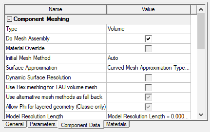
You can access the setting through Component Meshing properties.
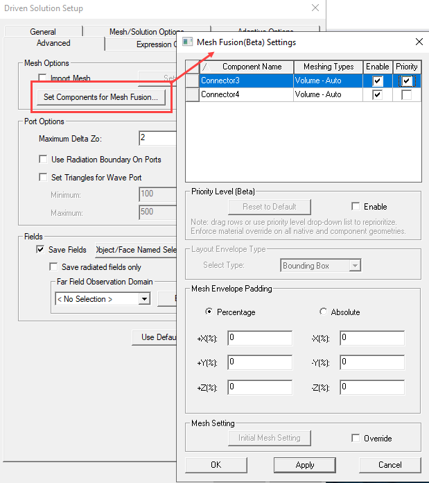
You can also access Mesh Fusion through the Advanced tab of the Solution Setup.
If a component does not meet the requirements for Mesh Fusion, the feature is disabled in the Do Mesh Fusion dialog and the Component Meshing properties.
Mesh Envelope Padding for Components without a User-defined Mesh Envelope
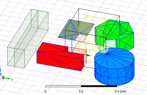
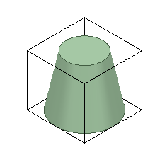
For each component used in mesh fusion, a tight bounding box is automatically created in the component’s target coordinate system. This tight region box is referred as ‘mesh envelope’. You can visualize such mesh envelope from the modeler window. See the example below.
To override this automation, users can manually assign mesh region to a single solid solve-inside model object which must contain all geometries in the design. Manual mesh region is needed in following scenarios:
- To avoid overlap with native geometry or another component
- To avoid contact with internal faces when possible. This will improve mesh quality leading to better solver performance.
For each component without a manually assigned mesh envelope, users can add padding to its mesh envelope in all 6 directions.
Note: The Mesh Envelope padding is applied in the component reference coordinate system. That is, think of the padding as applied in layout before bringing the component into HFSS.
The example below shows the same component discussed above with 20% padding added to all directions of its mesh envelope.
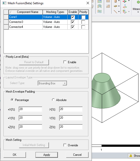
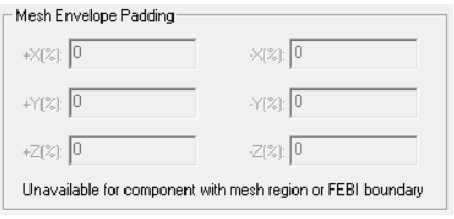
If a component has user-defined mesh envelope or is not a FEM volume component, the mesh envelop padding is disabled with a warning message.
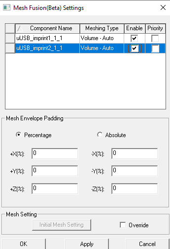
Mesh Method Override
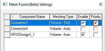
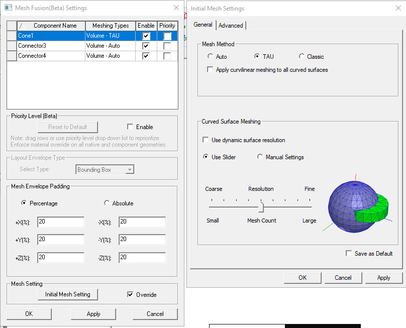
You can override the mesh method from the component definition in the Mesh Fusion Setting dialog box, accessed either through the 3D Component shortcut menu in the Project tree, or the Advanced tab of the an Advanced Solution Setup. This lets you deal with potential mesh failure based one specific mesh method when doing assembly meshing. If a failure happens using one method, you can easily switch the mesh method and try again. Selecting a component in the Mesh Fusion Setting dialog enables the region, where can check Override, and then select, Auto, TAU, or Classic. For convenience, the dialog also displays each component’s meshing method in its Meshing Type column.
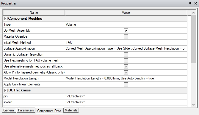
The Component Mesh settings will appear in the Component Properties window, Component Data tab.
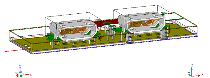
Example 1: USB Socket using Priority Level
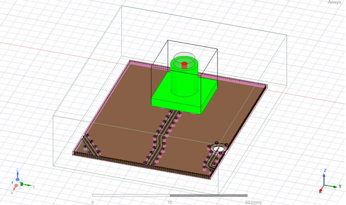
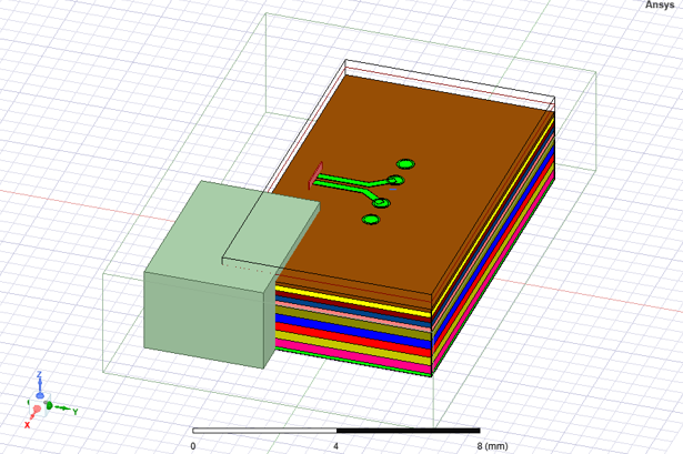
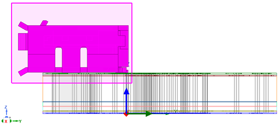
In the following example design, there are two micro-USB’s mounted on a mother board. The 2 USB’s are from two 3D components, and the mother board is from a third 3D component. Users would like to mark each of the three components as mesh fusion to mesh them separately.
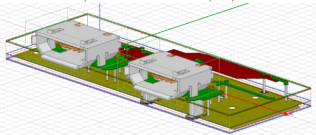
However, there are intersections in the design that must be resolved to use the mesh fusion technology. The below figure shows the right-side view of the design. The USB components have mesh fusion envelopes that intersect with the mother board. To resolve such intersections, the old way would be to manually cut out some bottom portion of the USB’s mesh fusion envelope.
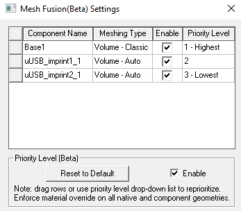
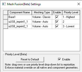
Using Priority Level, resolving such intersections is made easy. You can open the Set Do Mesh Assembly dialog and enable the component priority level. Then, you can assign the mother board component with the highest priority level as follows.
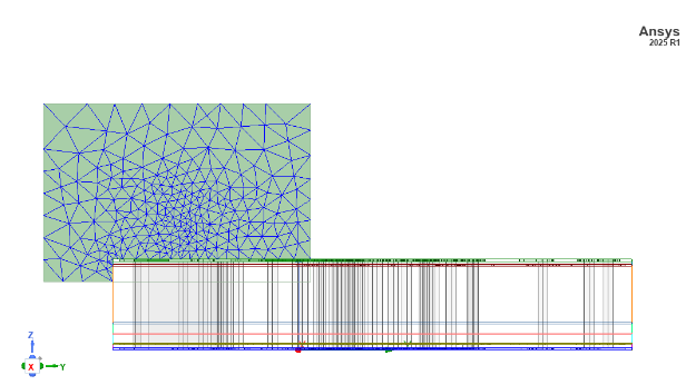
By doing so, the intersection is automatically resolved during simulation. According to the rules discussed in the earlier section, the mesh fusion envelope of the mother board component will cut off the mesh fusion envelopes of the USB components. The mesh plot of the USB components; envelopes is shown as follows.
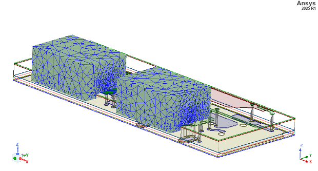
It is clear that the intersection is resolved by cutting the intersecting portion off the USB components’ envelopes.
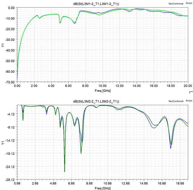
The simulation result of this case highly agrees with the result where all mesh fusion is turned off.
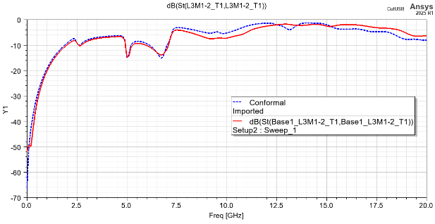
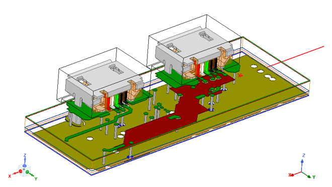
Example 2: USB Socket using Simple Priority
This example shows a circuit board with two USB sockets. The USB sockets are FEM components with custom defined air box as mesh regions.
You can set the Do Mesh Fusion property of each components by accessing the Do Mesh Fusion dialog through the Project tree shortcut menu for 3D Components.
The plots below show the comparison of terminal S parameters between designs in which the components are set for mesh fusion (solid line) or not (dashed line).