Mesh Assembly
With mesh assembly you can specify that multiple design modal FE-BI or IE/PO, SBR+ or FEM components and native regions are meshed independently to ensure very robust and rapid meshing. If a design contains multiple instances of a component, that component need only be meshed once. Parametric variations for one or more instances only affects the mesh of those instances.
The solver supports the following types of mesh assembly components.
- Volume component containing FEBI boundary
- Surface component (IE/PO)
- SBR+ component
- Volume components without FEBI.
Some of the benefits of mesh assembly are as follows:
- Systems with large variation in length scales can be successfully meshed. For example, in the case of a small 3D antenna touching an aircraft, you can mesh both the bodies separately and ensure a conformal mesh between them. That is, the triangulations in the contact area between the volume mesh of the 3D antenna component and the surface mesh of the aircraft are aligned resulting in a conformal mesh.
- You can select different meshers for each component via the Component Meshing properties.
That is, you can pick the Tau mesher for a given component and the
Classic mesher for another component, in order to ensure system meshing
is successful.
- Faster meshing for multiple instances of the same component is possible: only one initial mesh is created. For instance, when multiple identical antennas appear in a design, only one needs to be meshed.
- Mesh resuse enables fast placement studies. If you move a component, no re-meshing needs to be done. Also only the last adaptive mesh is used and no adaptive meshing of the component needs to done.
- Reused initial meshes are not impacted by any parametric variation. Suppose there are multiple components that are independently meshed and you make a parametric variation in one component, the remaining components are not remeshed. In this situation, the last adaptive mesh cannot be reused. Some examples of parametric variation can include increasing or decreasing the dimension of a geometry or changing the material properties.
- Mesh Assembly can be distributed.
You can access the Do Mesh Assembly feature through the Project tree shortcut menu for 3D Components, through the Advanced tab of the Solution Setup, or through Component Meshing properties.
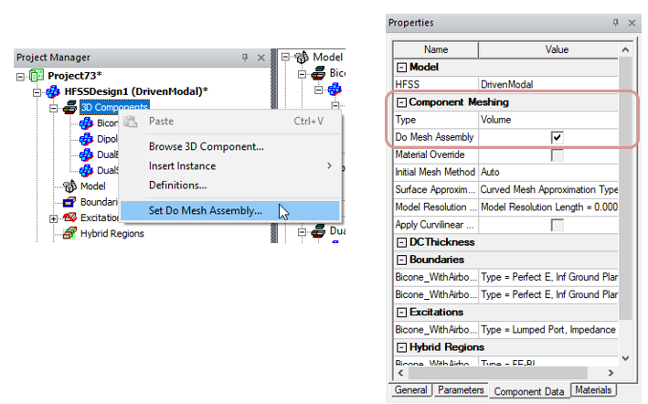
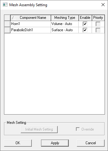
Selecting Set Do Mesh Assembly... opens a dialog which lists eligible components. Selecting a component enables the fields.
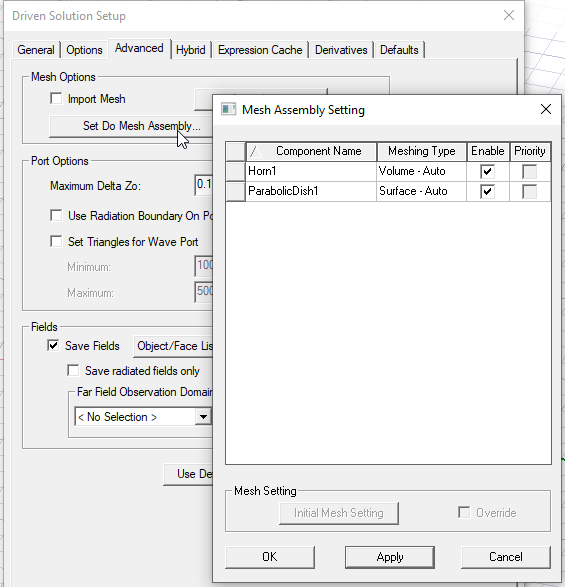
You can also access the Do Mesh Assembly Setting dialog through the Advanced tab of the Solution Setup.
If a component does not meet the requirement for mesh assembly, the feature is disabled in the Do Assembly Setting dialog and the Component Meshing properties.
Mesh Method Override
You can override the mesh method from the component definition in the Do Mesh Assembly Setting dialog box, accessed either through the 3D Component shortcut menu in the Project tree, 3D Components>Set Do Mesh Assembly, or the Advanced tab of the an Advanced Solution Setup. This lets you deal with potential mesh failure based one specific mesh method when doing assembly meshing. If a failure happens using one method, you can easily switch the mesh method and try again. Selecting a component in the Do Mesh Assembly Setting dialog enables Override checkbox. Checking the box enables the Intial Mesh Setting button, which opens the Initial Mesh Settings dialog box, where you can select and Apply, Auto, TAU, or Classic. For convenience, the dialog also displays each component’s meshing method in its Meshing Type column. The Component Priority checkboxes will be enabled if the components are valid for that feature.
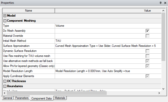
The overriding Component Mesh settings are shown in the Component Properties window, Component Data tab.
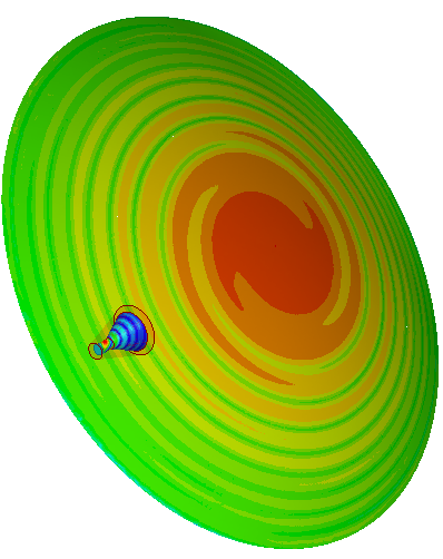
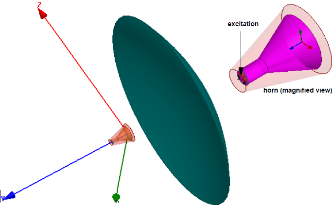
Example: Horn Antenna and a Dish
This example shows an electrically large problem for
the placement study of a horn antenna illuminating a dish, when the
antenna is moved along the y-axis. For such designs, meshing the horn
and the dish separately makes the simulation faster since only the currents
on the dish and on the radiation boundary of the horn need to be modeled.
Meshing the volume of the region between the horn and the dish to model
coupling occurring due to the currents on the dish and the radiation
volume bounding the horn is not required. With mesh assembly, you can
reuse the meshes of the individual components for performing placement
studies. The diameter of the reflector is 2000 mm and the adapt frequency
is defined to be 5 GHz. A design variable offset is defined to vary the
placement of the horn along the y axis.
To
use the mesh assembly feature, select the Do
Mesh Assembly option for the individual components of the
design as shown in the following figures:
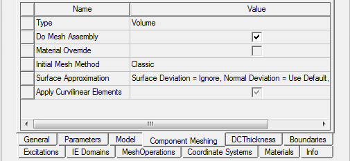
To access this feature, select component in the Project tree and select the Component Meshing tab in the Properties window. You can also view and set mesh assembly for all valid components in a design by using Set Do Mesh Assembly to open the Do Mesh Assembly dialog box, as shown above.
The radiation pattern for the three design variations
is shown below.
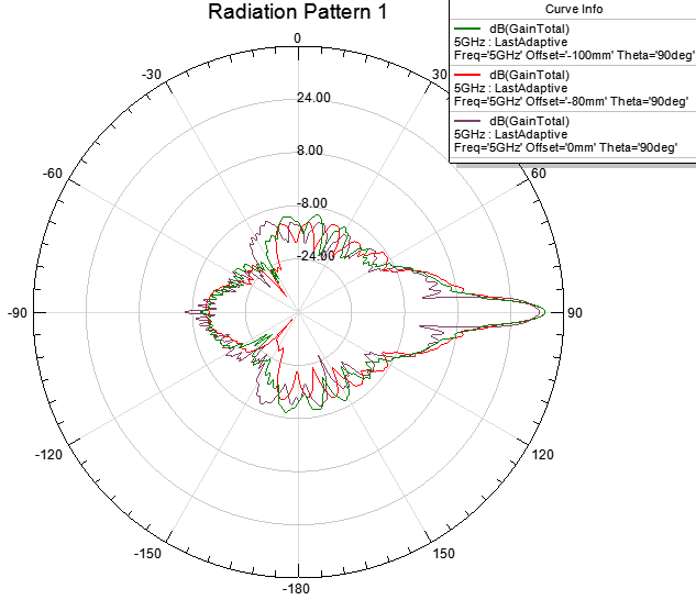
The plot for one such design variation, offset at 0 mm, is shown in the following figure.