Define an Integration Line
An integration line is a vector that can represent the following:
- A calibration line that specifies the direction of the excitation field pattern at a port. If you are analyzing more than one mode at a port, define a separate integration line for each mode; the orientation of the electric field differs from mode to mode.
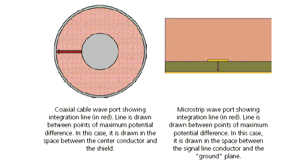
- An line along which to integrate E.dl to compute a voltage for Zpv or Zvi impedance of a port. In this case, select two points at which the voltage differential is expected to be at a maximum. For example, on a microstrip port, place one point in the center of the microstrip, and the other directly underneath it on the ground plane. In a rectangular waveguide, place the two points in the center of the longer sides.
Note:
For more information, see Wave Port Dialog For Modal Solutions. For definitions of how HFSS defines these Zpv and Zvi values, see Calculating the PV Impedance, and Calculating the VI Impedance.
To define an integration line:
- Double-click the port excitation from
the project tree to bring up the Wave Port dialog
box and click the Modes tab.
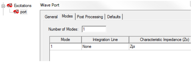
- From the Integration
Line column, select New Line.
The port dialog box disappears. If the Show Measure dialog option on the Modeler Options: Drawing tab is selected, the Measure Data dialog appears when you draw the vector.
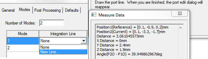
- Use the Measure
Data dialog to locate the start and end points and draw
the integration line.
Note:
The Measure Data dialog displays data for the face area, and the positions for the reference point (start point) and end point (end point) as you define them.