
Automation in Setting up an Open Problem
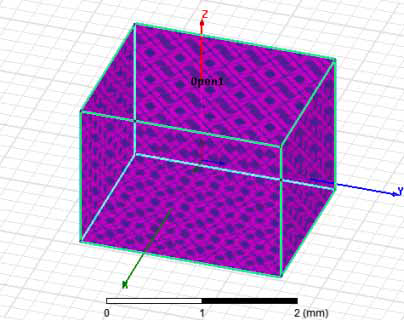
In an open problem, an air volume encompassing the outer radiating surfaces is modeled by a surrounding object. Radiation boundary conditions (ABC, PML or FEBI) are assigned to the outer radiating surfaces (i.e., faces of the region) to absorb all outgoing waves. HFSS users can use the Create Open Region command and Update Open Region Padding command to automate the setup of an open region problem. If you have specified the Auto Open Region check box in the Solution type, you will receive an error message. You must leave that check box unchecked to use this approach to automating an open problem.
You can access the Create Open Region command in three different ways:
- Right-click in the modeler window and select Create Open Region... from the context menu.
- Click HFSS>Model>Create Open Region...
- Right-click Model in the Project tree and select Create Open Region...
This displays the Create Open Region wizard.
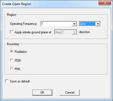
Your selections here guide the software in setting up the region and boundaries that are required to model the device as an open problem.
- Operating Frequency: This value is used to determine the region padding and CANNOT be parameterized. The default factory value is 1 GHz when there is no solve setup in the design.
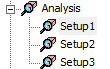
If you can created two or more solution setups, a pull-down provides you the ability to select the adaptive frequency. The default is to use the value from the first solve setup (in alphabetical order).
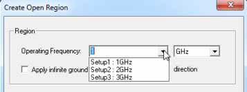
By option you can manually type in a value.
- Infinite ground plane can be specified at one of the 6 directions by checking Apply infinite ground and selecting from the drop-down menu.
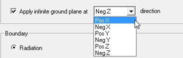
Default is at the Neg Z direction.
- Boundary can be one of:
Radiation, an absorbing boundary condition (ABC) that absorbs outgoing waves..
FEBI, finite element-boundary integral (FEBI) method. Unlike ABC and PML, the IE hybrid region can be of arbitrary shape, both concave and convex thus in some cases allowing the size of the finite element solution domain to be significantly reduced.
PML, perfectly matched layer, uses several layers of specialized materials that absorb outgoing waves.
Default region padding = min(L/2, Lambda/<Boundary Type Specific>) where L is the diagonal of device's bounding box and Lambda is the wavelength of the operating frequency. This is the same formulation used in the "auto-open" design mode. The padding for ABC = min(L/2, Lambda/3). The padding for FEBI is min(l/2, Lambda/8). The padding for PML = min(L/2, Lambda/4).
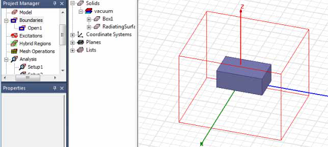
When you have made your selections, and OK the dialog, region is created and displayed as a wireframe with the boundary highlighted as selected.
Clicking outside the boundary de-selects the boundary. The boundary appears in the Project tree under boundaries (for Radiation and PML) or Hybrid regions (for FEBI) and under radiating surface in the history tree.
In the case of a PML, the Project manager window and history tree show the PML objects. The visibility of these objects are defaulted to off.
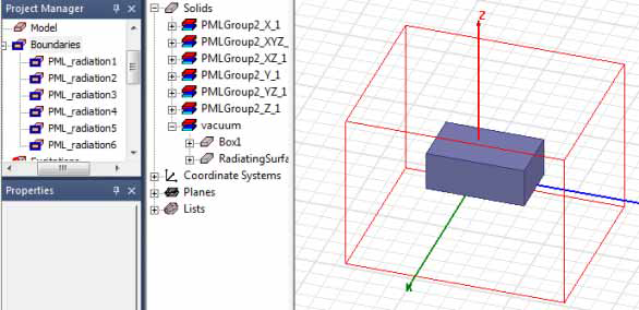
You can edit the properties of the created region objects in the history tree. You can also edit the properties of radiation and FEBI boundaries in the Project tree. More direct control of PML settings can be had by creating the PML boundaries via the PML wizard.
The region’s size is automatically updated if you change the size of your modeled device, but the region padding is not updated automatically.
Recalculate the Padding for Regions
The Update Open Region Padding command is enabled whenever there is a region object in a design. To Recalculate the Padding for Regions, select Update Open Region Padding.
- Right-click in the modeler window and select Update Open Region Padding... from the context menu.
- Click HFSS>Model>Update Open Region Padding...
- Right-click Model in the Project tree and select Update Open Region Padding...
This opens the Update Open Region dialog.
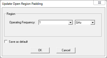
The function resembles that in the Create Open Region dialog box, where you can specify the operating frequency by selecting an already created setup or manually typed a value.
On OK, the region padding is updated based on the out-of-the box formulation min(L/2, Lambda/4) where L is the diagonal of the device's bounding box and Lambda is the wavelength of the adaptive frequency of the solve setup. The region is automatically resized when users edit the solve setup's adaptive frequency. Initial meshes and solutions are invalidated when the region is resized.
For example, suppose you began with a device diagonal size as 10 mm. You then launched the wizard and specified an operation frequency of 10 GHz. This ends with the region padding set to 5 mm. You then increase the device diagonal to 20 mm. The region is resized to encompass all geometries but padding remains at 5 mm. You then launch Update Open Region Padding and specify an operation frequency of 10 GHz On OK, the region padding is updated to 7.5 mm.