Antenna Radome SBR+ Using Fresnel Boundary
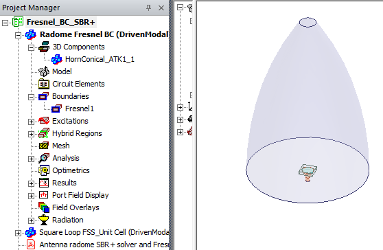
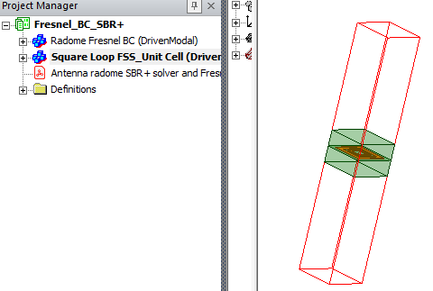
This example demonstrates how to apply Fresnel boundary condition in SBR+ to model an antenna radome. Frequency selective surface (FSS) was used for the antenna radome. The project Fresnel_BC_SBR+ consists of two designs: 1_Square Loop FSS_Unit Cell, and 2_Radome Fresnel BC. The example starts with HFSS Unit Cell design that contains a dual square loop FSS. The pdf attached to the project describes how to simulate the models.
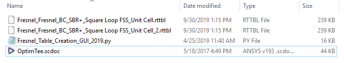
Once HFSS Unit Cell design is solved, script Fresnel_Table_Creation_GUI_2019.py should be run in order to obtain .rttbl table that is used to assign SBR+ Fresnel boundary condition for Radome design. The project is stored as an .aedtz archive in order to provide the scripts. Opening RadomeFresnel_BCPSBR+.aedtz from the Examples > HFSS > Antennas directory automatically asks you to specify a Restore location. In the save location you specify, you will see a restored_files folder. This folder contains the python script you need. Open the Antenna radome SBR+ solver and Fresnel Boundary Condition pdf for detailed instructions on how to work with the project and use the script.
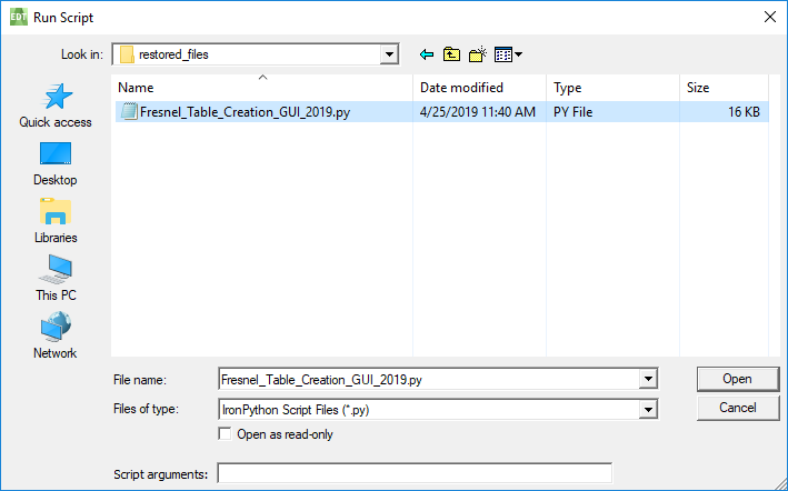
At one point you will use Tools > Run Script... to look in the restored_files folder. Set the Files of type line to Python to see and select the script.
The Radome is an SBR+ Region and all rays incident upon radome will be correctly captured even at obliques angles of incidence. With assigned Fresnel Table Boundary Condition to the radome, analyze the design. Make sure to use GPU for SBR+ solver if system supports it.