
Automated Port Tuning Tutorial
Introduction
This tutorial walks through an example of automated port tuning with Ansys Nuhertz Filtersolutions, Circuit, HFSS, and HFSS 3D Layout using the project titled Hairpin Tutorial found in C:\Program Files\ANSYS Inc\v###\AnsysEM\Nuhertz\Tutorials folder of your software download. The v### corresponds to the version number of your software download, e.g. v252 for version 25.2.
About Automated Port Tuning:
-
A fast means to optimize Ansys Nuhertz® FilterSolutions™ software planar HFSS and HFSS 3D Layout designs using Ansys Circuit software co-simulation.
-
Employs HFSS and HFSS 3D Layout internal tuning ports to adjust resonator length and separation.
-
Generally two to four electromagnetic (EM) simulations required for completion.
-
Eliminates or greatly reduces the need for traditional bulk EM optimization.
Steps:
-
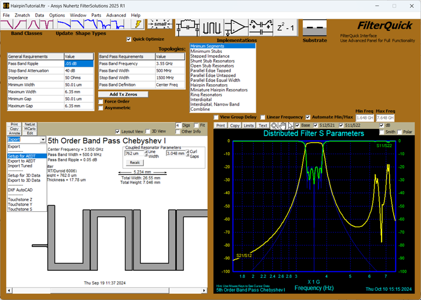
Open the Ansys Nuhertz® FilterSolutions™ software GUI. Select File > Open and navigate to the C:\Program Files\ANSYS Inc\v###\AnsysEM\Nuhertz\Tutorials directory. Open the Hairpin Tutorial filter design file. Design filter with ANFS and launch Ansys Electronics Desktop Export panel by selecting Export > Set up for AEDT.
-
Select Export > Set up for AEDT to launch the Ansys Electronics Desktop™ Export panel.
-
Export the design as a two-port file to HFSS 3D Layout. Setup the export as shown in the panel and use either Append to Ansys Desktopor Overwrite to Ansys Desktop. Give the project and design a unique name by using the field in the upper right-hand corner. Once the project is created use the Simulate now button to start the analysis.

-
Set up the Export for Automated Port Tuning with HFSS 3D Layout.
-
Select Default Configurations in the AEDT Export Panel.

-
Select Enable in the Automated Port Tuning Options group box.

-
Select Export with Tuning Port Format in the Automated Port Tuning Options group box; Deselect Use Horizontal Series Ports.

-
Choose Append to Ansys Desktop.

This step will launch Ansys Electronics Desktop software with the Ansys Nuhertz FilterSolutions project. It will generate both a HFSS 3D Layout design and a linked Circuit design.

-
- Ansys Nuhertz FilterSolutions software will be used to drive the solution of these designs in Ansys Electronics Desktop Software. Choose Simulate Full to solve both the HFSS and Circuit design. The Simulate Tune option will solve the Circuit design only.Note: SimulateTune will automatically simulate HFSS 3D Layout if the HFSS 3D Layout is not valid.Note: SimulateTune will NOT simulate HFSS, regardless of whether the HFSS simulation data is valid or not.

-
Display the results of both the circuit simulation and the original two port simulation. The frequency responses should be the same. Sometimes the internal ports used in the port tuning approach will generate a frequency shift relative to the two port solution. To correct this shift there is a variable in the Circuit design named Kdebed. This variable can be tuned to assure the two responses line up.
-
In Ansys Electronics Desktop software's Project Manager, expand the FilterSolutions_Tune project, right-click Optimetrics, select Tuning.

-
In the Tune dialogue, deselect Browse available variations.

-
Use the slider to tune Kdebed until the center frequency of the tuning port design matches the center frequency of the design with no tuning ports. Leave all other variables at their original value. The default value of Kdebed is 0.7, for this filter that value is OK.


-
-
Optimize the tuning port design by selecting Optimize in the Ansys Nuhertz FilterSolutions' Export panel. The optimization is run in the Circuit model so it is relatively fast.

-
Reconstruct the optimized design: After the optimization process completes, select Import and Reexport Over to send the reconstructed design immediately back to Ansys Electronics Desktop software. The physical variables in the HFSS 3D Layout model are adjusted based on the optimization results in the Circuit design.

-
Use the Simulate Full option in the AEDT Export Options window to run the updated simulation. The response in the Circuit design should be like the display below.

You can choose to stop here or try to further improve the return loss and bandwidth
-
To further improve the response choose Optimize in the Ansys Nuhertz FilterSolutions' AEDT Export Options window. Once the optimization has completed use Import and Reexport Over and then Simulate Full. The response in the Circuit design should be like the display below.

-
Repeat Optimize, Import and Reexport Over, and Simulate Full to yield a frequency response and return loss like shown below.

-
At this point the response is satisfactory. The next step is to use the tuned variables to generate a two port model of the filter.
-
In the Ansys Nuhertz FilterSolutions' AEDT Export Options window, select the Import Tuned Variables option.

-
Uncheck the Export with Tuning Port Format and then Append to Ansys Desktop.

-
Use the Simulate Now button in the upper left had corner of the AEDT Export Options window.The final response of the tuned two port model is shown below:

-