
TRL Stripline Transmission Line
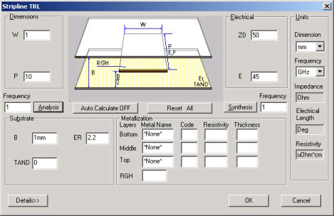
|
Keyword |
Default |
Unit |
Description |
|
W |
Req (Phys) |
m |
Conductor width |
|
P |
0 |
m |
Physical length of transmission line |
|
Z0 |
Req (Elec) |
ohm |
Transmission line impedance |
|
E |
0 |
deg |
Electrical length of transmission line |
|
Frequency |
0 |
Hz |
Analysis frequency |
|
ER |
Req |
|
Relative dielectric constant |
|
B |
Req |
m |
Substrate thickness |
|
TAND |
0 |
|
Dielectric loss tangent |
|
RGH |
0 |
m |
Rms surface roughness |
Synthesis and Analysis
- For synthesis of stripline transmission lines, the parameters Z0, B, and ER must be entered prior to clicking Synthesis. The width, W, is computed.
- For analysis, the parameters W, B, and ER must be entered prior to clicking Analysis. The impedance, Z0, is computed. The frequency is used if entered; otherwise, 0 Hz is used in the calculation.
- Conversion from electrical length, E, to physical length, P, can be performed by entering values for E and Frequency. Click Synthesis to compute P. Similarly, to convert from physical length to electrical length, enter values for P and Frequency, and click Analysis to compute E.
Dielectric Substrates
A dielectric substrate is defined by the parameters B, ER, and TAND. The substrate is assumed to be lossless unless TAND is specified and greater than zero.
Conductor Metalization
- Conductor specification is performed in the Metalization control group. If the conductor is not specified, the conductor loss is zero and no thickness corrections are made to the line’s propagation characteristics. Up to three conductors of different metals and thicknesses can be specified.
- Metalization rms surface roughness, RGH, can be specified for additional conductor losses due to imperfect metal surfaces. RGH is specified in terms of rms variation from an ideal flat surface.
Sweep Options
Parameters that can be swept for the stripline transmission line are:
Frequency
Width, W
The order shown is the order used to generate output data when multiple parameters are swept simultaneously. See the Sweep Entries topic for further information.
Limitations
Error less than 0.5% for W/B < 10.
Example
To select the stripline medium, pull down the Structure menu, select Stripline, and click Single. Set the units to mm and GHz. Enter the following parameters to synthesize a stripline:
Impedance, Z0: 50 ohms
Dielectric constant, ER: 2.2
Substrate thickness, B: 1.27 mm
Click Synthesis to determine the width, W, of the transmission line:
Width, W: 1.05 mm
Since stripline is a TEM structure and does not vary with frequency, perform a sweep analysis on the width of the strip instead. Type 0.5, 3.0, 0.5 into the W group box to sweep the line’s width from 0.5 mm to 3.0 mm in steps of 0.5 mm. Be sure to supply information on the line’s metalization and losses:
Metal: Cu 0.01 mm
TAND: 0.001
Clicking Analysis yields the following:
Single Stripline
B = 1.270mm ER = 2.20 TAND = 0.00100 T/B = 0.0079
Freq Width W/B Z0 D Loss C Loss T Loss
ghz mm Ohms dB/mm dB/mm dB/mm
0.0 0.500 0.394 74.86 0.0000 0.0002 0.0002
0.0 1.000 0.787 50.69 0.0000 0.0002 0.0002
0.0 1.500 1.181 38.41 0.0000 0.0001 0.0001
0.0 2.000 1.575 30.93 0.0000 0.0001 0.0001
0.0 2.500 1.969 25.90 0.0000 0.0001 0.0001
0.0 3.000 2.362 22.28 0.0000 0.0001 0.0001
Change the frequency to 10 GHz and click Analysis
again:
Single Stripline
B = 1.270mm ER = 2.20 TAND = 0.00100 T/B = 0.0079
Freq Width W/B Z0 D Loss C Loss T Loss
ghz mm Ohms dB/mm dB/mm dB/mm
10.0 0.500 0.394 74.86 0.0014 0.0029 0.0043
10.0 1.000 0.787 50.69 0.0014 0.0024 0.0038
10.0 1.500 1.181 38.41 0.0014 0.0022 0.0035
10.0 2.000 1.575 30.93 0.0014 0.0020 0.0034
10.0 2.500 1.969 25.90 0.0014 0.0019 0.0033
10.0 3.000 2.362 22.28 0.0014 0.0019 0.0032
Notice that the impedances are the same for DC or 10 GHz, but the conductor loss calculations differ significantly due to the skin effect.