Differential TDR
Open the TDR Schematic project from its file in the Examples directory.
- From the File menu, select Open Examples to open an explorer window.
- Open Circuit, then Signal Integrity, and select the file
TDR_Example.aedt. Click Open.
Expand the TDR_Example icon and the 2_Differential icon. The differential TDR schematic appears in the design window:

The differential TDR consists of two channels, each with a pulse source, an internal impedance equal to 0.5Z0 ohm, a transmission line with 0.5Z0-ohm impedance and with 0.5-ns delay, and two voltage probes, Vexcited_pos or Vexcited_neg for the step voltage and Vdetected_pos or Vdetected_neg for the reflected voltage. (Z0 is the TDR component parameter.)
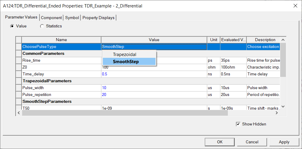
The TDR component provides two options for the pulse type: Trapezoidal and SmoothStep. SmoothStep provides a more realistic step input and allows control of the rise interval.
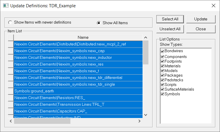
- Click Tools > Project Tools > Update Definitions.
- In the Update Definitions dialog, select Show All Items, Select All, then click Update . Close the dialog once updates are successful.
-
Right-click the TDR model symbol and click Properties to open the properties dialog.
-
Click the Value field for ChoosePulseType to view the two options. Select SmoothStep, click Apply, then OK to close the dialog.
The Device Under Test (DUT) is microstrip coupled line pair and a termination network. The transient analysis sweeps the spacing between the coupled lines, which shows how the spacing affects the differential impedance, Zdiff.
- Select the coupled lines. The Property window shows that the spacing parameter SP has been defined with a local variable.
- Expand the Analysis icon, double-click
on the Transient analysis setup, and verify the sweep of the spacing
variable.

- In the Project Tree, right-click Transient and select Analyze. The analysis runs to completion.

- Expand the Reports icon and right-click
on the Zdiff report setup. Select Modify Report to open
the Report Setup.

- Click New Report to generate
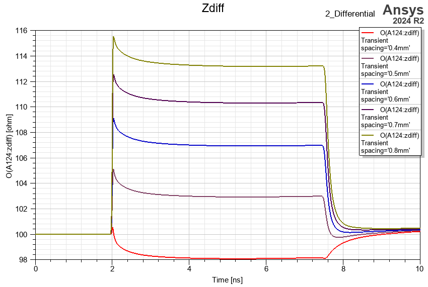
the report:

The TDR analysis shows how the spacing affects the differential impedance. Using the Trapezoidal waveform, the reflection timings are expected at 2*(Total Delay).