
IBIS I/O Wizard Signal Setup
To configure signal pin assignments using the I/O Wizard window, select the selected pins and click Set as signal pins ; this opens the Signal Setup window for the selected pins.
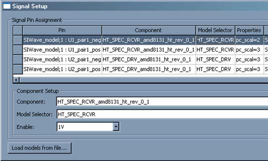
Fields in the Signal Setup window are editable. Also select multiple rows and click the Component Setup fields at bottom to make multiple changes to many pins simultaneously.
- The Component field lists components already imported, and represents either an IBIS pin or an IBIS model, depending on the component selected.
- The ModelSelector field lists the available models for this component (e.g., the model_sel property of the IBIS component).
- The Pullup to pin field lists non-signal pins (e.g., Power or Ground) to connect to the Pull Up pin for the attached buffer. The default is a Power/Ground pin. Alternately, select to select any one-port circuit in the project for the connection.
- The Pulldownto pin field follows the same rules as Pullup to pin, with regards to the Pull Down assignment for the attached buffer.
- For I/O Buffers, there is an Enable field that can either be 0V or 1V (depending on how the buffer is configured to operate). The Enable field is only visible for I/O buffers.
- Also load additional IBIS files by clicking Load models from file to open the Import IBIS File window.
Click OK to close the window and implement any changes that have been configured.