
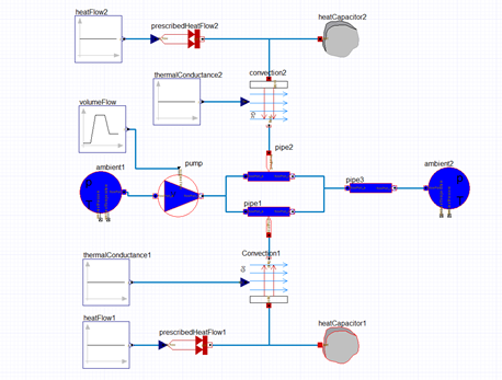
Placing Modelica Components for the Parallel Pump Drop Out Model
All of the required components for the Controlled Tanks example can be found in the Modelica library in the locations shown in the following table.
| Component Instance | Location in Library |
|---|---|
| heatFlow1, heatFlow2 | Modelica/Blocks/Sources/Constant |
| prescribedHeatFlow, prescribedHeatFlow2 | Modelica/Thermal/HeatTransfer/Sources/PrescribedHeatFlow |
| heatCapacitor1, heatCapacitor2 | Modelica/Thermal/HeatTransfer/Components/HeatCapacitor |
| convection1, convection2 | Modelica/Thermal/HeatTransfer/Components/Convection |
| thermalConductance1, thermalConductance2 | Modelica/Blocks/Sources/Constant |
| volumeFlow | Modelica/Thermal/FluidHeatFlow/Examples/Utilities/DoubleRamp |
| ambient1, ambient2 | Modelica/Thermal/FluidHeatFlow/Sources/Ambient |
| pump | Modelica/Thermal/FluidHeatFlow/Sources/VolumeFlow |
| pipe1, pipe2 | Modelica/Thermal/FluidHeatFlow/Components/HeatedPipe |
| pipe3 | Modelica/Thermal/FluidHeatFlow/Components/IsolatedPipe |
- Locate each of the components in the library.
-
Drag and drop the components into the Diagram Editor in the Modelica Environment, arranging them as shown in the figure below. Press Esc after placing each component to stop the placement action. Connections will be added later.
- You can change the instance names for a components by clicking on the component to display its Properties window. You can enter the desired instanceName in the associated Value field on the Properties tab
- Press Esc to complete each action.
Next, you will add connections between the various Parallel Pump Drop Out components.