
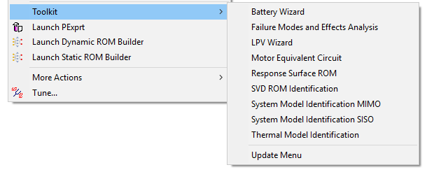
System Model Identification MIMO
Select the System Model Identification MIMO option under Twin Builder > Toolkit to generate a multiple-input and multiple-output (MIMO) linear system ROM, using the input and step response files that you create and provide.
Creating Files Needed for ROM Creation
To use System Model Identification MIMO to create a MIMO state space model, create the following files:
- Input_PortNames.txt
- Input_StepInputValues.txt
- step response data files
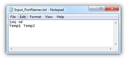
Input_PortNames.txt
The Input_PortNames.txt file contains port names you want to show as the Twin Builder component pin names; these names must match the step response file name. The file must contain two rows; the first row lists all the inputs, and the second row lists all the outputs as shown below.
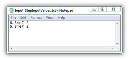
Input_StepInputValues.txt
The Input_StepInputValues.txt file identifies the step inputs used to generate the LTI ROM. It is formatted as a matrix, and it must be compatible with Input_PortNames.txt.
- The first element (1,1) is the step input used to generate IHG.Temp1.out.
- (2,1) is the step input used to generate IHG.Temp2.out.
- (1,2) is the step input used to generate HF.Temp1.out, and so on.
The same input is typically used for generating all the output step responses in one simulation, so each column should have the same value if that is the case. For example:
Step Response Data Files
You must generate step response data files independently for each input.
For example, to generate step responses for a multi-input system, each time only one input should be activated with a step input. To simplify the process, you can export all the desired output step responses for each specific input. The step response tabular data must be formatted with time unit as sec and must be saved with the name formatted as inputname.outputname.out, defined in Input_PortNames.txt.
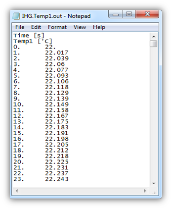
After saving all the step responses to the OUT files, you must manually reformat these files according to these requirements:
- The labels must be in the first line and second line of the file.
- The data section must have two columns separated by a tab or space.
Here is an example of a data file:
The step response file must have enough information to represent the system characteristics.
After creating the files, you must copy them into the same location.
Using System Model Identification MIMO
After you have created the files required for creating the MIMO linear state space ROM, use System Model Identification Toolkit - MIMO to generate an export file in an SML, MATLAB, or Modelica+FMU format. Click Help to access information about the options and inputs.
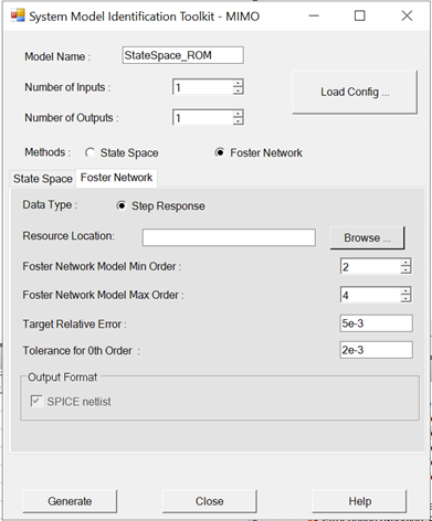
- In the Model Name box, you can edit the default name of the generated component. You cannot use spaces, hyphens, or other special characters.
- In the Number of Inputs box, you can edit the number of inputs to be used in Twin Builder. The number of inputs provided must match the data of the prepared files.
- In the Number of Outputs box, you can edit the number of outputs to be used in Twin Builder. The number of outputs provided must match the data of the prepared files.
- Click Load Config to select a configuration file and populate the dialog box.
- In the Methods section, select the State Space or Foster Network radio button. The tab fields below the radio buttons change slightly based on your choice.
- In the Resource Location field, browse to the location where you placed the Input PortNames.txt and Input_StepInputValues.txt data files. The Step Response option is selected by default.
- The fields in the Options section are:
Parameter Description State Space Model Min Order or Foster Network Model Min Order Minimum order used. A higher order gives more accurate results, but takes longer to simulate. If you enter 0, then a contribution might be ignored based on the Tolerance for 0th Order specified. State Space Model Max Order or Foster Network Model Max Order Maximum order used. 40th order is set to be the maximum. Target Relative Error This is used to determine the order by the algorithm in the limit range given by [minorder maxorder]. Tolerance for 0th Order This is used to ignore certain contributions if its value is less than the tolerance multiplied by the largest contribution. - The choices in the Output Format section change depending on whether you chose the State Space or Foster Network radio button in step 5. If you chose State Space, your choices are SML, Matlab, or FMU. Raw state space format is always exported. When you select Modelica, a drop-down lets you select 1.0 or 2.0 for the FMU. If you chose Foster Network, your only choice is SPICE netlist.
- Click Generate for the toolkit to generate the chosen output format in the resource location:
- SML – SML components load into Twin Builder.
- Matlab – A MATLAB m file is exported and the raw matrices are generated and written separately.
- FMU – Modelica components load into Twin Builder and the FMU version you indicated is also exported to the step response data location. When you select this check box, the next two options appear.
- FMU Version – Select whether to generate and load FMU 1.0 or FMU 2.0.
- Sparse Matrix/Dense Matrix – Choose if the Modelica components generate in regular dense matrix or sparse matrix. Sparse matrix is suggested for a state space model with many zero cells.
Note:
The B matrix and D matrix expand to take reference values as extra constant inputs. The toolkit already embedded the reference values for SML model and Modelica model (as well as in the FMU version). For MATLAB file and raw matrices, you must manually assign correct reference values to output pins.
- SPICE netlist – A foster network model in .spc format is created in the working directory and imported into Twin Builder.
- Click Close.